Information injection-pump assembly
ZEXEL
101601-5140
1016015140
Rating:
Service parts 101601-5140 INJECTION-PUMP ASSEMBLY:
1.
_
6.
COUPLING PLATE
7.
COUPLING PLATE
8.
_
9.
_
11.
Nozzle and Holder
236001800A
12.
Open Pre:MPa(Kqf/cm2)
19.6(200)
15.
NOZZLE SET
Cross reference number
ZEXEL
101601-5140
1016015140
Zexel num
Bosch num
Firm num
Name
101601-5140
INJECTION-PUMP ASSEMBLY
Calibration Data:
Adjustment conditions
Test oil
1404 Test oil ISO4113 or {SAEJ967d}
1404 Test oil ISO4113 or {SAEJ967d}
Test oil temperature
degC
40
40
45
Nozzle and nozzle holder
105780-8140
Bosch type code
EF8511/9A
Nozzle
105780-0000
Bosch type code
DN12SD12T
Nozzle holder
105780-2080
Bosch type code
EF8511/9
Opening pressure
MPa
17.2
Opening pressure
kgf/cm2
175
Injection pipe
Outer diameter - inner diameter - length (mm) mm 6-2-600
Outer diameter - inner diameter - length (mm) mm 6-2-600
Overflow valve
131424-5720
Overflow valve opening pressure
kPa
255
221
289
Overflow valve opening pressure
kgf/cm2
2.6
2.25
2.95
Tester oil delivery pressure
kPa
157
157
157
Tester oil delivery pressure
kgf/cm2
1.6
1.6
1.6
Direction of rotation (viewed from drive side)
Right R
Right R
Injection timing adjustment
Direction of rotation (viewed from drive side)
Right R
Right R
Injection order
1-4-2-6-
3-5
Pre-stroke
mm
3.1
3.07
3.13
Beginning of injection position
Drive side NO.1
Drive side NO.1
Difference between angles 1
Cal 1-4 deg. 60 59.75 60.25
Cal 1-4 deg. 60 59.75 60.25
Difference between angles 2
Cyl.1-2 deg. 120 119.75 120.25
Cyl.1-2 deg. 120 119.75 120.25
Difference between angles 3
Cal 1-6 deg. 180 179.75 180.25
Cal 1-6 deg. 180 179.75 180.25
Difference between angles 4
Cal 1-3 deg. 240 239.75 240.25
Cal 1-3 deg. 240 239.75 240.25
Difference between angles 5
Cal 1-5 deg. 300 299.75 300.25
Cal 1-5 deg. 300 299.75 300.25
Injection quantity adjustment
Adjusting point
-
Rack position
9.4
Pump speed
r/min
1500
1500
1500
Average injection quantity
mm3/st.
62.6
60.6
64.6
Max. variation between cylinders
%
0
-3.5
3.5
Basic
*
Fixing the rack
*
Standard for adjustment of the maximum variation between cylinders
*
Injection quantity adjustment_02
Adjusting point
-
Rack position
8.6+-0.5
Pump speed
r/min
250
250
250
Average injection quantity
mm3/st.
9
7.5
10.5
Max. variation between cylinders
%
0
-10
10
Fixing the rack
*
Standard for adjustment of the maximum variation between cylinders
*
Remarks
Adjust only variation between cylinders; adjust governor according to governor specifications.
Adjust only variation between cylinders; adjust governor according to governor specifications.
Injection quantity adjustment_03
Adjusting point
A
Rack position
R1(9.4)
Pump speed
r/min
1500
1500
1500
Average injection quantity
mm3/st.
62.6
61.6
63.6
Basic
*
Fixing the lever
*
Injection quantity adjustment_04
Adjusting point
B
Rack position
(R1+0.05
)
Pump speed
r/min
900
900
900
Average injection quantity
mm3/st.
56
54
58
Fixing the lever
*
Injection quantity adjustment_05
Adjusting point
I
Rack position
-
Pump speed
r/min
100
100
100
Average injection quantity
mm3/st.
90
90
100
Fixing the lever
*
Rack limit
*
Timer adjustment
Pump speed
r/min
1200+50
Advance angle
deg.
0
0
0
Remarks
Start
Start
Timer adjustment_02
Pump speed
r/min
1500
Advance angle
deg.
4
3.7
4.3
Remarks
Finish
Finish
Test data Ex:
Governor adjustment

N:Pump speed
R:Rack position (mm)
(1)Torque cam stamping: T1
(2)RACK LIMIT
----------
T1=B67
----------
----------
T1=B67
----------
Speed control lever angle

F:Full speed
I:Idle
(1)Stopper bolt set position 'H'
----------
----------
a=34deg+-3deg b=34deg+-5deg
----------
----------
a=34deg+-3deg b=34deg+-5deg
Stop lever angle
N:Pump normal
S:Stop the pump.
(1)Set the normal set bolt.
(2)Engine normal
(3)Engine stop
----------
----------
a=(12deg) b=(22deg)+-5deg c=35deg+-5deg d=40deg+-5deg
----------
----------
a=(12deg) b=(22deg)+-5deg c=35deg+-5deg d=40deg+-5deg
0000001501 LEVER
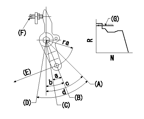
(A) Pump's normal lever
(B) Engine's normal lever
(C) Engine stop
(D) Pump stop
(E) Stop direction (perpendicular)
(F) Normal set bolt
(g) rack limit
Stop lever angle and engine's normal setting procedures
(1)After completing adjustment, confirm that the pump's normal lever angle and the pump's stop lever angle are within the specifications in the figure above.
(2)Before setting the rack limit, screw in the normal set bolt, return it 1 turn from point I and then fix the normal set bolt using the locknut. (engine normal)
(3)With the lever at idle and N = Na, pull the stop lever in the stop direction so that the rack position is the non-injection position. Measure the angle at this time. (Engine stop)
(4)Set the rack limit. (Point I adjustment)
----------
Na=250r/min ra=40mm a=(12deg) b=(22deg)+-5deg c=35deg+-5deg d=40deg+-5deg
----------
----------
Na=250r/min ra=40mm a=(12deg) b=(22deg)+-5deg c=35deg+-5deg d=40deg+-5deg
----------
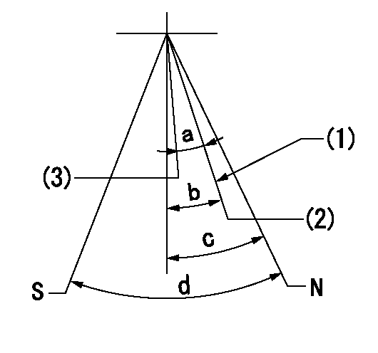
Timing setting

(1)Pump vertical direction
(2)Position of gear's standard threaded hole at No 1 cylinder's beginning of injection
(3)-
(4)-
----------
----------
a=(70deg)
----------
----------
a=(70deg)
Information:
Start By:
Do not let the tops of the nozzles turn while the fuel lines are loosened. The nozzles will be damaged if the top of the nozzle turns in the body. Defective fuel nozzles will damage the engine due to improper spray patterns.
a. remove fuel injection lines
Keep all parts clean from contaminants. Contaminants put into the system may cause rapid wear and shortened component life.
1. Remove clamp (1). 2. Install tool (A). Turn screw (2) out until the button on the screw almost makes contact with the inside of the nozzle puller. Tilt the tool approximately 45° and place it over the nozzle.3. Tilt the nozzle puller (A) up so the inside lip of the puller is under the stepped diameter of the nozzle.4. Turn screw (2) down until the button goes into the bolt hole for the nozzle hold down clamp.
Do not exceed a torque of 17 N m (13 lb ft) on the screw in tooling (A) to remove the nozzle. Added force can cause the stem of the nozzle to bend or break off.
5. Turn screw (2) to lift the nozzle out of its bore. If necessary, after the nozzle is loose in its bore, move it up and down to help loosen any carbon and make removal easier. 6. If the nozzle can not be removed with tooling (A), tooling (B) must be used. When tooling (B) is used, the nozzle normally can not be used again, and a new nozzle will need to be installed as a replacement.
Hold tool (B) so the center line of tool (B) is the same as the extended center line of fuel injection nozzle (2). This will prevent distortion of the fuel injection nozzle which can cause the nozzle to bend or break off.
7. Remove the protective cap and install tooling (B).8. Use the slide hammer to remove fuel injection nozzle (3).9. Remove the compression seal.10. For nozzles removed using tool (A), remove the carbon dam seal on the end of the nozzle. The following steps are for the installation of the fuel injection nozzles. Tool (C) must be modified by drilling it out to a diameter of 8.5 mm (.344 in) and to a depth of 1.5 mm (.060 in) before it can be used on the 8N7002 Fuel Injection Nozzle.11. Use tool (C) to install carbon dam seal (4).12. To clean the nozzles, see Special Instruction SEHS7292 for the use of tooling (D).13. Install new compression seal (5). 14. Use tool (E) to clean the bore for the fuel injection nozzle. 15. Install fuel injection nozzle (6).
Do not let the tops of the fuel nozzles turn when the fuel lines are tightened. The nozzles will be damaged if the top of the nozzle turns in the body.
End By:a. install fuel injection lines
Have questions with 101601-5140?
Group cross 101601-5140 ZEXEL
Hino
Hino
Hino
101601-5140
INJECTION-PUMP ASSEMBLY