Information injection-pump assembly
ZEXEL
101601-5124
1016015124
HINO
220004892A
220004892a
Rating:
Service parts 101601-5124 INJECTION-PUMP ASSEMBLY:
1.
_
6.
COUPLING PLATE
7.
COUPLING PLATE
8.
_
9.
_
11.
Nozzle and Holder
236001730A
12.
Open Pre:MPa(Kqf/cm2)
21.6(220)
15.
NOZZLE SET
Cross reference number
ZEXEL
101601-5124
1016015124
HINO
220004892A
220004892a
Zexel num
Bosch num
Firm num
Name
101601-5124
220004892A HINO
INJECTION-PUMP ASSEMBLY
W06E * K
W06E * K
Calibration Data:
Adjustment conditions
Test oil
1404 Test oil ISO4113 or {SAEJ967d}
1404 Test oil ISO4113 or {SAEJ967d}
Test oil temperature
degC
40
40
45
Nozzle and nozzle holder
105780-8140
Bosch type code
EF8511/9A
Nozzle
105780-0000
Bosch type code
DN12SD12T
Nozzle holder
105780-2080
Bosch type code
EF8511/9
Opening pressure
MPa
17.2
Opening pressure
kgf/cm2
175
Injection pipe
Outer diameter - inner diameter - length (mm) mm 6-2-600
Outer diameter - inner diameter - length (mm) mm 6-2-600
Overflow valve
131424-5720
Overflow valve opening pressure
kPa
255
221
289
Overflow valve opening pressure
kgf/cm2
2.6
2.25
2.95
Tester oil delivery pressure
kPa
157
157
157
Tester oil delivery pressure
kgf/cm2
1.6
1.6
1.6
Direction of rotation (viewed from drive side)
Right R
Right R
Injection timing adjustment
Direction of rotation (viewed from drive side)
Right R
Right R
Injection order
1-4-2-6-
3-5
Pre-stroke
mm
3.1
3.07
3.13
Beginning of injection position
Drive side NO.1
Drive side NO.1
Difference between angles 1
Cal 1-4 deg. 60 59.75 60.25
Cal 1-4 deg. 60 59.75 60.25
Difference between angles 2
Cyl.1-2 deg. 120 119.75 120.25
Cyl.1-2 deg. 120 119.75 120.25
Difference between angles 3
Cal 1-6 deg. 180 179.75 180.25
Cal 1-6 deg. 180 179.75 180.25
Difference between angles 4
Cal 1-3 deg. 240 239.75 240.25
Cal 1-3 deg. 240 239.75 240.25
Difference between angles 5
Cal 1-5 deg. 300 299.75 300.25
Cal 1-5 deg. 300 299.75 300.25
Injection quantity adjustment
Adjusting point
-
Rack position
8.9
Pump speed
r/min
900
900
900
Average injection quantity
mm3/st.
47.4
45.4
49.4
Max. variation between cylinders
%
0
-3.5
3.5
Basic
*
Fixing the rack
*
Standard for adjustment of the maximum variation between cylinders
*
Injection quantity adjustment_02
Adjusting point
H
Rack position
8+-0.5
Pump speed
r/min
250
250
250
Average injection quantity
mm3/st.
6.8
5.3
8.3
Max. variation between cylinders
%
0
-10
10
Fixing the rack
*
Standard for adjustment of the maximum variation between cylinders
*
Injection quantity adjustment_03
Adjusting point
A
Rack position
R1(8.9)
Pump speed
r/min
900
900
900
Average injection quantity
mm3/st.
47.4
46.4
48.4
Basic
*
Fixing the lever
*
Injection quantity adjustment_04
Adjusting point
B
Rack position
R1+0.25
Pump speed
r/min
1500
1500
1500
Average injection quantity
mm3/st.
58.3
54.3
62.3
Fixing the lever
*
Injection quantity adjustment_05
Adjusting point
C
Rack position
R1-0.15
Pump speed
r/min
600
600
600
Average injection quantity
mm3/st.
36.7
32.7
40.7
Fixing the lever
*
Injection quantity adjustment_06
Adjusting point
D
Rack position
(R1+0.1)
Pump speed
r/min
1200
1200
1200
Average injection quantity
mm3/st.
52.2
48.2
56.2
Fixing the lever
*
Injection quantity adjustment_07
Adjusting point
E
Rack position
R1+0.3
Pump speed
r/min
400
400
400
Average injection quantity
mm3/st.
29.2
25.2
33.2
Fixing the lever
*
Injection quantity adjustment_08
Adjusting point
I
Rack position
-
Pump speed
r/min
100
100
100
Average injection quantity
mm3/st.
99
99
109
Fixing the lever
*
Rack limit
*
Timer adjustment
Pump speed
r/min
1050--
Advance angle
deg.
0
0
0
Remarks
Start
Start
Timer adjustment_02
Pump speed
r/min
1000
Advance angle
deg.
0.3
Timer adjustment_03
Pump speed
r/min
1500
Advance angle
deg.
3.5
3.2
3.8
Remarks
Finish
Finish
Test data Ex:
Governor adjustment
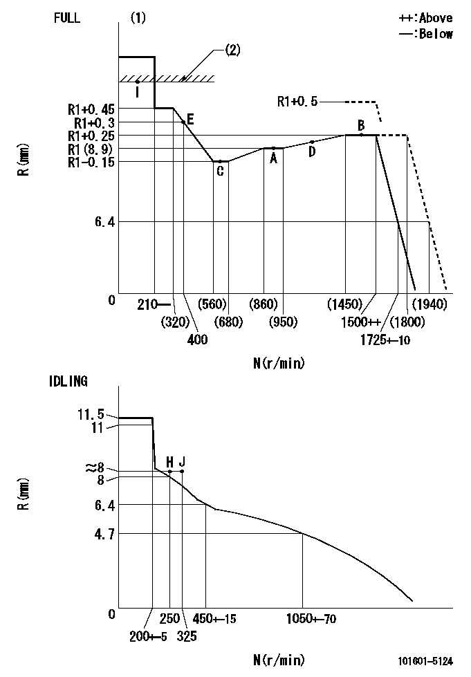
N:Pump speed
R:Rack position (mm)
(1)Torque cam stamping: T1
(2)RACK LIMIT
----------
T1=B98
----------
----------
T1=B98
----------
Speed control lever angle

F:Full speed
I:Idle
(1)Stopper bolt set position 'H'
----------
----------
a=32deg+-3deg b=34deg+-5deg
----------
----------
a=32deg+-3deg b=34deg+-5deg
Stop lever angle

N:Pump normal
S:Stop the pump.
----------
----------
a=40deg+-5deg b=40deg+-5deg
----------
----------
a=40deg+-5deg b=40deg+-5deg
0000001501 TAMPER PROOF
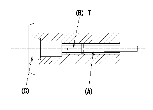
1. Method for setting tamperproof proofing
(1)After governor adjustment (torque cam phase adjustment), move the load lever to increase the full rack position to Ra.
(2)At pump speed N1, push in the screw (A) until the rack position is Rb.
(3)Temporarily caulk using the tip of a screwdriver
(4)Confirm that the rack at that time is at Rc.
(5)Lock using setscrew (B). (Tightening torque = T)
(6)Next, coat (C) with adhesive and then pressfit.
(7)Then, readjust the full rack position using the load lever.
----------
N1=1500r/min Ra=(0.4)mm Rb=R1(8.9)+0.5mm Rc=R1(8.9)+0.5mm
----------
T=3.4~4.9N-m(0.35~0.5Kgf-m)
----------
N1=1500r/min Ra=(0.4)mm Rb=R1(8.9)+0.5mm Rc=R1(8.9)+0.5mm
----------
T=3.4~4.9N-m(0.35~0.5Kgf-m)
Timing setting

(1)Pump vertical direction
(2)Position of gear's standard threaded hole at No 1 cylinder's beginning of injection
(3)-
(4)-
----------
----------
a=(70deg)
----------
----------
a=(70deg)
Information:
Overheating
Possible Causes/Corrections Low Coolant LevelIf the coolant level is too low, not enough coolant will go through the engine and radiator. This lack of coolant will not take enough heat from the engine and there will not be enough flow of coolant through the radiator to release the heat into the cooling air. Low coolant level is caused by leaks or wrong filling of the radiator. With the engine cool, be sure that coolant can be seen at the low end of the fill neck on the radiator top tank. Defective Temperature GaugeA temperature gauge which does not work correctly will not show the correct temperature. If the temperature gauge shows that the coolant temperature is too hot but other conditions are normal, either install a gauge you know is good or check the cooling system with the 4C6500 Digital Thermometer Group. Dirty RadiatorCheck the radiator for debris between the fins of the radiator core which prevents free air flow through the radiator core. Check the radiator for debris, dirt, or deposits on the inside of the radiator core which prevents free flow of coolant through the radiator. Loose Belt(s)Loose fan or water pump belts will cause a reduction in air or water flow. Tighten the belts according to Belt Tension Chart that is shown in Specification Section of this Service Manual. Defective Hose(s)Defective hoses with leaks can normally be seen. Hoses that have no visual leaks can "collapse" (pull together) during operation and cause a restriction in the flow of coolant. Hoses become soft and/or get cracks after a period of time. Hoses must be changed after 50,000 miles or a year of use. The inside can become loose, and the loose particles of the hose can cause a restriction in the flow of coolant. Shunt Line RestrictionA restriction of the shunt line from the radiator top tank to the engine front cover, or a shunt line not installed correctly, will cause a reduction in water pump efficiency. The result will be low coolant flow and overheating. Shutters Not Opening CorrectlyCheck the opening temperature of the shutters. The shutters must be completely closed at a temperature below the fully open temperature of the water temperature regulators. Also, verify that fan control switches or viscous fans are operating correctly. Defective Water Temperature RegulatorsA regulator that does not open, or only opens part of the way, can cause above normal heating. To test the thermostats, see the Testing and Adjusting Section of this Service Manual. Defective Water PumpA water pump with a loose impeller does not pump enough coolant for correct engine cooling. A loose impeller can be found by removing the water pump, and by pushing the shaft back and pulling it forward. If the impeller has no damage, check the impeller clearance. The clearance between the impeller and the housing is 0.56 to 1.50 mm (.022 to .059 in). Air In Cooling SystemAir can get into the cooling system in different ways. The most common causes are
Possible Causes/Corrections Low Coolant LevelIf the coolant level is too low, not enough coolant will go through the engine and radiator. This lack of coolant will not take enough heat from the engine and there will not be enough flow of coolant through the radiator to release the heat into the cooling air. Low coolant level is caused by leaks or wrong filling of the radiator. With the engine cool, be sure that coolant can be seen at the low end of the fill neck on the radiator top tank. Defective Temperature GaugeA temperature gauge which does not work correctly will not show the correct temperature. If the temperature gauge shows that the coolant temperature is too hot but other conditions are normal, either install a gauge you know is good or check the cooling system with the 4C6500 Digital Thermometer Group. Dirty RadiatorCheck the radiator for debris between the fins of the radiator core which prevents free air flow through the radiator core. Check the radiator for debris, dirt, or deposits on the inside of the radiator core which prevents free flow of coolant through the radiator. Loose Belt(s)Loose fan or water pump belts will cause a reduction in air or water flow. Tighten the belts according to Belt Tension Chart that is shown in Specification Section of this Service Manual. Defective Hose(s)Defective hoses with leaks can normally be seen. Hoses that have no visual leaks can "collapse" (pull together) during operation and cause a restriction in the flow of coolant. Hoses become soft and/or get cracks after a period of time. Hoses must be changed after 50,000 miles or a year of use. The inside can become loose, and the loose particles of the hose can cause a restriction in the flow of coolant. Shunt Line RestrictionA restriction of the shunt line from the radiator top tank to the engine front cover, or a shunt line not installed correctly, will cause a reduction in water pump efficiency. The result will be low coolant flow and overheating. Shutters Not Opening CorrectlyCheck the opening temperature of the shutters. The shutters must be completely closed at a temperature below the fully open temperature of the water temperature regulators. Also, verify that fan control switches or viscous fans are operating correctly. Defective Water Temperature RegulatorsA regulator that does not open, or only opens part of the way, can cause above normal heating. To test the thermostats, see the Testing and Adjusting Section of this Service Manual. Defective Water PumpA water pump with a loose impeller does not pump enough coolant for correct engine cooling. A loose impeller can be found by removing the water pump, and by pushing the shaft back and pulling it forward. If the impeller has no damage, check the impeller clearance. The clearance between the impeller and the housing is 0.56 to 1.50 mm (.022 to .059 in). Air In Cooling SystemAir can get into the cooling system in different ways. The most common causes are
Have questions with 101601-5124?
Group cross 101601-5124 ZEXEL
Hino
Hino
101601-5124
220004892A
INJECTION-PUMP ASSEMBLY
W06E
W06E