Information injection-pump assembly
BOSCH
9 400 614 600
9400614600
ZEXEL
101601-5092
1016015092
HINO
220801301A
220801301a
Rating:
Service parts 101601-5092 INJECTION-PUMP ASSEMBLY:
1.
_
6.
COUPLING PLATE
7.
COUPLING PLATE
8.
_
9.
_
11.
Nozzle and Holder
12.
Open Pre:MPa(Kqf/cm2)
21.6(220)

15.
NOZZLE SET
Cross reference number
BOSCH
9 400 614 600
9400614600
ZEXEL
101601-5092
1016015092
HINO
220801301A
220801301a
Zexel num
Bosch num
Firm num
Name
101601-5092
9 400 614 600
220801301A HINO
INJECTION-PUMP ASSEMBLY
W06D * K
W06D * K
Calibration Data:
Adjustment conditions
Test oil
1404 Test oil ISO4113 or {SAEJ967d}
1404 Test oil ISO4113 or {SAEJ967d}
Test oil temperature
degC
40
40
45
Nozzle and nozzle holder
105780-8140
Bosch type code
EF8511/9A
Nozzle
105780-0000
Bosch type code
DN12SD12T
Nozzle holder
105780-2080
Bosch type code
EF8511/9
Opening pressure
MPa
17.2
Opening pressure
kgf/cm2
175
Injection pipe
Outer diameter - inner diameter - length (mm) mm 6-2-600
Outer diameter - inner diameter - length (mm) mm 6-2-600
Overflow valve
131424-5720
Overflow valve opening pressure
kPa
255
221
289
Overflow valve opening pressure
kgf/cm2
2.6
2.25
2.95
Tester oil delivery pressure
kPa
157
157
157
Tester oil delivery pressure
kgf/cm2
1.6
1.6
1.6
Direction of rotation (viewed from drive side)
Right R
Right R
Injection timing adjustment
Direction of rotation (viewed from drive side)
Right R
Right R
Injection order
1-4-2-6-
3-5
Pre-stroke
mm
3.1
3.07
3.13
Beginning of injection position
Drive side NO.1
Drive side NO.1
Difference between angles 1
Cal 1-4 deg. 60 59.75 60.25
Cal 1-4 deg. 60 59.75 60.25
Difference between angles 2
Cyl.1-2 deg. 120 119.75 120.25
Cyl.1-2 deg. 120 119.75 120.25
Difference between angles 3
Cal 1-6 deg. 180 179.75 180.25
Cal 1-6 deg. 180 179.75 180.25
Difference between angles 4
Cal 1-3 deg. 240 239.75 240.25
Cal 1-3 deg. 240 239.75 240.25
Difference between angles 5
Cal 1-5 deg. 300 299.75 300.25
Cal 1-5 deg. 300 299.75 300.25
Injection quantity adjustment
Adjusting point
-
Rack position
8.7
Pump speed
r/min
1000
1000
1000
Average injection quantity
mm3/st.
46.6
44.6
48.6
Max. variation between cylinders
%
0
-3.5
3.5
Basic
*
Fixing the rack
*
Standard for adjustment of the maximum variation between cylinders
*
Injection quantity adjustment_02
Adjusting point
H
Rack position
8+-0.5
Pump speed
r/min
250
250
250
Average injection quantity
mm3/st.
8
6.5
9.5
Max. variation between cylinders
%
0
-10
10
Fixing the rack
*
Standard for adjustment of the maximum variation between cylinders
*
Injection quantity adjustment_03
Adjusting point
A
Rack position
R1(8.7)
Pump speed
r/min
1000
1000
1000
Average injection quantity
mm3/st.
46.6
45.6
47.6
Basic
*
Fixing the lever
*
Injection quantity adjustment_04
Adjusting point
B
Rack position
R1-0.3
Pump speed
r/min
1600
1600
1600
Average injection quantity
mm3/st.
45.2
43.2
47.2
Fixing the lever
*
Injection quantity adjustment_05
Adjusting point
C
Rack position
R1+0.2
Pump speed
r/min
1300
1300
1300
Average injection quantity
mm3/st.
52
50
54
Fixing the lever
*
Injection quantity adjustment_06
Adjusting point
D
Rack position
R1-0.15
Pump speed
r/min
650
650
650
Average injection quantity
mm3/st.
38
36
40
Fixing the lever
*
Injection quantity adjustment_07
Adjusting point
I
Rack position
13.5+-0.
5
Pump speed
r/min
100
100
100
Average injection quantity
mm3/st.
95
95
105
Fixing the lever
*
Rack limit
*
Injection quantity adjustment_08
Adjusting point
E
Rack position
R1+0.35
Pump speed
r/min
400
400
400
Average injection quantity
mm3/st.
28
24
32
Fixing the lever
*
Timer adjustment
Pump speed
r/min
1300+50
Advance angle
deg.
0
0
0
Remarks
Start
Start
Timer adjustment_02
Pump speed
r/min
1600
Advance angle
deg.
3.5
3.2
3.8
Remarks
Finish
Finish
Test data Ex:
Governor adjustment
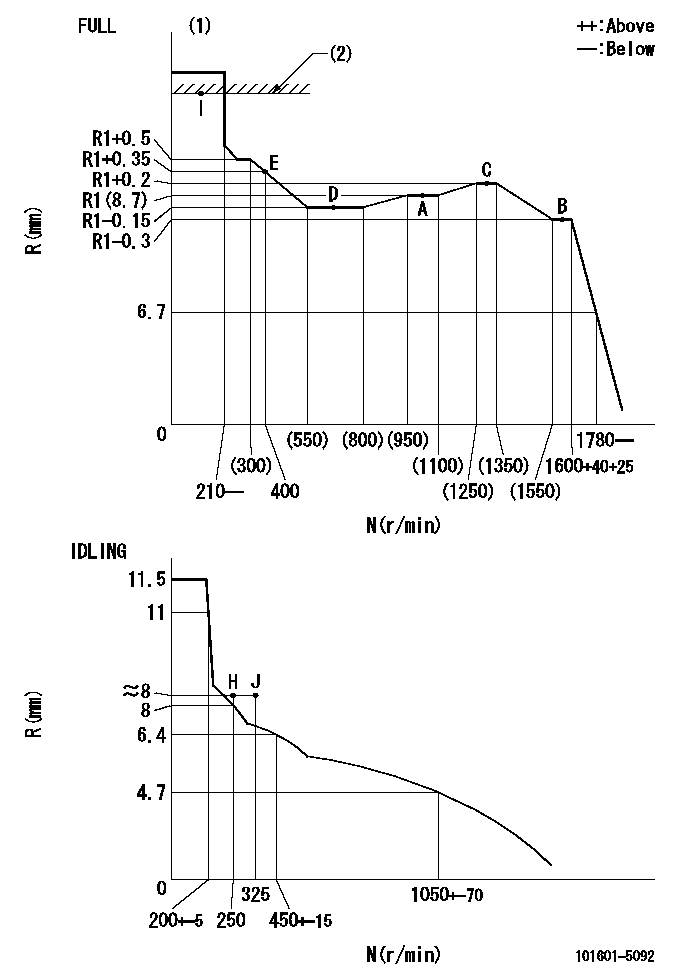
N:Pump speed
R:Rack position (mm)
(1)Torque cam stamping: T1
(2)RACK LIMIT
----------
T1=A76
----------
----------
T1=A76
----------
Speed control lever angle

F:Full speed
I:Idle
(1)Stopper bolt set position 'H'
----------
----------
a=33deg+-3deg b=34deg+-5deg
----------
----------
a=33deg+-3deg b=34deg+-5deg
Stop lever angle

N:Pump normal
S:Stop the pump.
----------
----------
a=40deg+-5deg b=40deg+-5deg
----------
----------
a=40deg+-5deg b=40deg+-5deg
0000001501 ACS

(A) Set screw
(B) Push rod 1
(C) Push rod 2
(D) Cover
1. Aneroid compensator unit adjustment
(1)Select the push rod 2 to obtain L2.
(2)Screw in (A) to obtain L1.
2. Adjustment when mounting the governor.
(1)Set the speed of the pump to N1 r/min and fix the control lever at the full set position.
(2)Screw in the aneroid compensator to obtain the performance shown in the graph above.
(3)As there is hysterisis, measure when the absolute pressure drops.
(4)Hysterisis must not exceed rack position = h1.
----------
N1=1000r/min L1=(1.5)mm L2=7+-0.5mm h1=-
----------
Ra=R1(8.7)mm Rb=(7.8)mm Pa=(84.5)kPa((634)mmHg) Pb=61.6kPa(462mmHg) Q1=46.6+-1cm3/1000st Q2=32.6+-1cm3/1000st
----------
N1=1000r/min L1=(1.5)mm L2=7+-0.5mm h1=-
----------
Ra=R1(8.7)mm Rb=(7.8)mm Pa=(84.5)kPa((634)mmHg) Pb=61.6kPa(462mmHg) Q1=46.6+-1cm3/1000st Q2=32.6+-1cm3/1000st
Timing setting

(1)Pump vertical direction
(2)Position of gear's standard threaded hole at No 1 cylinder's beginning of injection
(3)-
(4)-
----------
----------
a=(70deg)
----------
----------
a=(70deg)
Information:
The problems in this section are problems that do come about and are normally called "low power". These problems are not necessarily more common than engine problems, but they are possible problems which you need to read and check before an engine is disassembled.Read all of the items but make sure the first three are checked completely before making any engine test. Possible Causes/Corrections Tachometer ErrorTo check, connect a tachometer of known accuracy to the engine. Run the engine and make a comparison of the readings of the vehicle and test tachometers. If vehicle tachometer is defective, make repairs as necessary or install a new tachometer. Engine Operated At High AltitudeLess oxygen at higher altitudes causes the engine horsepower to go down. There is no effect on the horsepower of the engine for the first 2280 m (7500 ft) above sea level of operation. Brakes Do Not Completely ReleaseCheck the brakes by feeling all the brake drums. If the brakes of a wheel do not completely release, the brake drum for that wheel will be hotter than the brake drums for the other wheels. With the truck lifted with a jack, the wheels must have free rotation when turned by hand. Extra Engine Driven EquipmentAir compressors, hydraulic pumps, alternator, and other engine driven equipment that has damage, or that was not installed correctly, or that is not in correct adjustment, can take more horsepower to drive than expected. If necessary, disconnect the equipment and test the engine. Speedometer ErrorA defective speedometer does not give the correct speed or the correct indication of fuel consumption. An indication of low speed can cause the operator to feel that he has a power problem. Speeds Too HighThe need for more horsepower is easy to see as the speed of the vehicle is increased. This is especially true if the front of the vehicle has a large surface area. Application personnel can give you the horsepower necessary for different vehicle designs at different speeds. Overload On VehicleApplication personnel can give you the horsepower needs for different vehicles. High Moving ResistanceSoft ground conditions cause a need for more horsepower. To see if the problem is the engine, test the vehicle on a surface known to be good, or test on a chassis dynamometer. High Wind ResistanceThe horsepower needs for a truck can be divided into two parts. Part of the horsepower is used to move the vehicle and part is used to get through the resistance of the wind. The horsepower necessary to get through the resistance of the wind will increase as the vehicle is used at higher speeds. Vehicles with a large front area have a higher wind resistance and take more horsepower than those with a small front area. Some types of trucks, for example those used for the transportation of automobiles and or boats have high wind resistance even if the front area is small. Moving against the wind has the same effect on wind resistance as does higher
Have questions with 101601-5092?
Group cross 101601-5092 ZEXEL
Hino
Hino
Hino
Hino
Hino
Hino
Hino
Hino
Hino
101601-5092
9 400 614 600
220801301A
INJECTION-PUMP ASSEMBLY
W06D
W06D