Information injection-pump assembly
BOSCH
9 400 619 588
9400619588
ZEXEL
101601-5091
1016015091
Rating:
Service parts 101601-5091 INJECTION-PUMP ASSEMBLY:
1.
_
6.
COUPLING PLATE
7.
COUPLING PLATE
8.
_
9.
_
11.
Nozzle and Holder
12.
Open Pre:MPa(Kqf/cm2)
21.6{220}
15.
NOZZLE SET
Cross reference number
BOSCH
9 400 619 588
9400619588
ZEXEL
101601-5091
1016015091
Zexel num
Bosch num
Firm num
Name
Calibration Data:
Adjustment conditions
Test oil
1404 Test oil ISO4113 or {SAEJ967d}
1404 Test oil ISO4113 or {SAEJ967d}
Test oil temperature
degC
40
40
45
Nozzle and nozzle holder
105780-8140
Bosch type code
EF8511/9A
Nozzle
105780-0000
Bosch type code
DN12SD12T
Nozzle holder
105780-2080
Bosch type code
EF8511/9
Opening pressure
MPa
17.2
Opening pressure
kgf/cm2
175
Injection pipe
Outer diameter - inner diameter - length (mm) mm 6-2-600
Outer diameter - inner diameter - length (mm) mm 6-2-600
Overflow valve
131424-5720
Overflow valve opening pressure
kPa
255
221
289
Overflow valve opening pressure
kgf/cm2
2.6
2.25
2.95
Tester oil delivery pressure
kPa
157
157
157
Tester oil delivery pressure
kgf/cm2
1.6
1.6
1.6
Direction of rotation (viewed from drive side)
Right R
Right R
Injection timing adjustment
Direction of rotation (viewed from drive side)
Right R
Right R
Injection order
1-4-2-6-
3-5
Pre-stroke
mm
3.1
3.07
3.13
Beginning of injection position
Drive side NO.1
Drive side NO.1
Difference between angles 1
Cal 1-4 deg. 60 59.75 60.25
Cal 1-4 deg. 60 59.75 60.25
Difference between angles 2
Cyl.1-2 deg. 120 119.75 120.25
Cyl.1-2 deg. 120 119.75 120.25
Difference between angles 3
Cal 1-6 deg. 180 179.75 180.25
Cal 1-6 deg. 180 179.75 180.25
Difference between angles 4
Cal 1-3 deg. 240 239.75 240.25
Cal 1-3 deg. 240 239.75 240.25
Difference between angles 5
Cal 1-5 deg. 300 299.75 300.25
Cal 1-5 deg. 300 299.75 300.25
Injection quantity adjustment
Adjusting point
-
Rack position
8.7
Pump speed
r/min
1000
1000
1000
Average injection quantity
mm3/st.
46.6
44.6
48.6
Max. variation between cylinders
%
0
-3.5
3.5
Basic
*
Fixing the rack
*
Standard for adjustment of the maximum variation between cylinders
*
Injection quantity adjustment_02
Adjusting point
H
Rack position
8+-0.5
Pump speed
r/min
250
250
250
Average injection quantity
mm3/st.
8
6.5
9.5
Max. variation between cylinders
%
0
-10
10
Fixing the rack
*
Standard for adjustment of the maximum variation between cylinders
*
Injection quantity adjustment_03
Adjusting point
A
Rack position
R1(8.7)
Pump speed
r/min
1000
1000
1000
Average injection quantity
mm3/st.
46.6
45.6
47.6
Basic
*
Fixing the lever
*
Injection quantity adjustment_04
Adjusting point
B
Rack position
R1-0.3
Pump speed
r/min
1600
1600
1600
Average injection quantity
mm3/st.
45.2
43.2
47.2
Fixing the lever
*
Injection quantity adjustment_05
Adjusting point
C
Rack position
R1+0.2
Pump speed
r/min
1300
1300
1300
Average injection quantity
mm3/st.
52
50
54
Fixing the lever
*
Injection quantity adjustment_06
Adjusting point
D
Rack position
R1-0.15
Pump speed
r/min
650
650
650
Average injection quantity
mm3/st.
38
36
40
Fixing the lever
*
Injection quantity adjustment_07
Adjusting point
I
Rack position
13.5+-0.
5
Pump speed
r/min
100
100
100
Average injection quantity
mm3/st.
95
95
105
Fixing the lever
*
Rack limit
*
Injection quantity adjustment_08
Adjusting point
E
Rack position
R1+0.35
Pump speed
r/min
400
400
400
Average injection quantity
mm3/st.
28
24
32
Fixing the lever
*
Timer adjustment
Pump speed
r/min
1300+50
Advance angle
deg.
0
0
0
Remarks
Start
Start
Timer adjustment_02
Pump speed
r/min
1600
Advance angle
deg.
3.5
3.2
3.8
Remarks
Finish
Finish
Test data Ex:
Governor adjustment
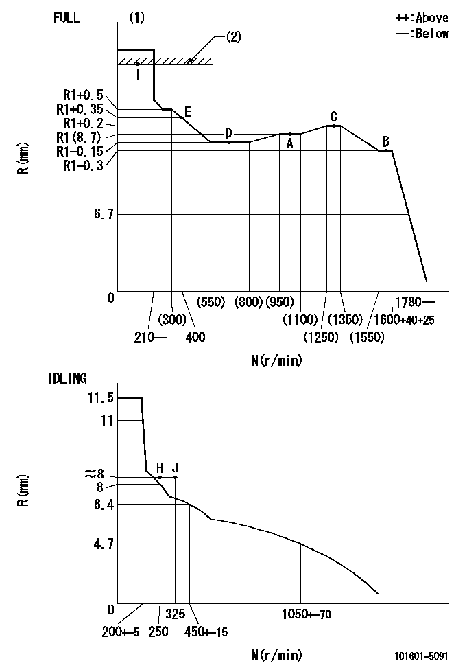
N:Pump speed
R:Rack position (mm)
(1)Torque cam stamping: T1
(2)RACK LIMIT
----------
T1=A76
----------
----------
T1=A76
----------
Speed control lever angle

F:Full speed
I:Idle
(1)Stopper bolt set position 'H'
----------
----------
a=33deg+-3deg b=34deg+-5deg
----------
----------
a=33deg+-3deg b=34deg+-5deg
Stop lever angle

N:Pump normal
S:Stop the pump.
----------
----------
a=40deg+-5deg b=40deg+-5deg
----------
----------
a=40deg+-5deg b=40deg+-5deg
0000001501 ACS

(A) Set screw
(B) Push rod 1
(C) Push rod 2
(D) Cover
1. Aneroid compensator unit adjustment
(1)Select the push rod 2 to obtain L2.
(2)Screw in (A) to obtain L1.
2. Adjustment when mounting the governor.
(1)Set the speed of the pump to N1 r/min and fix the control lever at the full set position.
(2)Screw in the aneroid compensator to obtain the performance shown in the graph above.
(3)As there is hysterisis, measure when the absolute pressure drops.
(4)Hysterisis must not exceed rack position = h1.
----------
N1=1000r/min L1=(1.5)mm L2=7+-0.5mm h1=-
----------
Ra=R1(8.7)mm Rb=(7.8)mm Pa=(84.5)kPa((634)mmHg) Pb=61.6kPa(462mmHg) Q1=46.6+-1cm3/1000st Q2=32.6+-1cm3/1000st
----------
N1=1000r/min L1=(1.5)mm L2=7+-0.5mm h1=-
----------
Ra=R1(8.7)mm Rb=(7.8)mm Pa=(84.5)kPa((634)mmHg) Pb=61.6kPa(462mmHg) Q1=46.6+-1cm3/1000st Q2=32.6+-1cm3/1000st
Timing setting

(1)Pump vertical direction
(2)Position of gear's standard threaded hole at No 1 cylinder's beginning of injection
(3)-
(4)-
----------
----------
a=(70deg)
----------
----------
a=(70deg)
Information:
The Primary Engine Checks consist of quick and easy procedures that could identify the problem with a minimum loss of time. Always make these checks before starting the more involved troubleshooting procedures.Whenever a problem is found and corrected, always run the test again to that point to be sure there is not a combination of problems. When the problem has been corrected and the complaint resolved, stop the test. Do not continue through the complete procedure unless it is necessary. Possible Causes/Corrections Prestart ChecksMake sure the air filter elements are in good condition and are not plugged. Also, make sure the engine oil and coolant are at the correct levels. Check Accelerator LinkageTo check the linkage adjustment, push the pedal down until it hits the stop. If the linkage adjustment is correct, the governor linkage will move to the break-over position when the pedal is against the stop. This is shown by clearance on both sides of the tang (see the illustration). When there is clearance on both sides of the tang, the governor linkage is adjusted correctly to permit the engine to operate at high idle. If clearance is not present on both sides of the tang, adjust the governor linkage to give the needed clearance.
Governor Control Linkage Adjustment
(1) Clearance on both sides of tang. (2) Governor control linkage. (3) Pedal (full travel). (4) Governor control. (5) Lever assembly. Check Vehicle TachometerInstall the 6V3121 Multitach Group. Start the engine and make sure that the vehicle tachometer is accurately indicating engine rpm. Some electric vehicle tachometers can be adjusted. Correct the tachometer as required. A defective tachometer can cause operation at the wrong engine rpm, this can give the feel of low power. Check For Air In The FuelDisconnect the fuel return line. With the engine in operation, let the fuel from the injection pump housing flow into a container. Look for air bubbles in the fuel coming from the return line. Approximately 5 to 100 visible air bubbles in the fuel is normal. If there is excessive air in the fuel find the cause and correct it. Such as checking all fuel lines and connections for leaks and repair or replacement of parts as needed. Check Fuel API Gravity RatingCaterpillar diesel engines are set in production to produce rated power with a fuel of 35 API gravity (0.85 specific gravity). This limit provides a grade of fuel that aids engine starting and avoids vapor lock. Fuel with higher API gravities (i.e., lower specific gravities), will produce less horsepower at the factory power setting and vice versa for lower than 35 API gravity fuels. The engine fuel setting should not be adjusted to compensate for a power loss with fuels lighter than 35 as fuel system component life may be decreased.For more information see Special Instruction Form No. SEHS7067, Fuel Recommendations For Caterpillar Diesel Engines. Also, Special Instruction, Form No. SEHS6947 has fuel correction factors and tables. Check For Proper Fuel Heater ApplicationMake sure that fuel heaters are