Information injection-pump assembly
BOSCH
9 400 614 598
9400614598
ZEXEL
101601-5073
1016015073
HINO
220801321A
220801321a

Rating:
Include in #1:
106682-9340
as _
Cross reference number
BOSCH
9 400 614 598
9400614598
ZEXEL
101601-5073
1016015073
HINO
220801321A
220801321a
Zexel num
Bosch num
Firm num
Name
101601-5073
9 400 614 598
220801321A HINO
INJECTION-PUMP ASSEMBLY
W06D K
W06D K
Calibration Data:
Adjustment conditions
Test oil
1404 Test oil ISO4113 or {SAEJ967d}
1404 Test oil ISO4113 or {SAEJ967d}
Test oil temperature
degC
40
40
45
Nozzle and nozzle holder
105780-8140
Bosch type code
EF8511/9A
Nozzle
105780-0000
Bosch type code
DN12SD12T
Nozzle holder
105780-2080
Bosch type code
EF8511/9
Opening pressure
MPa
17.2
Opening pressure
kgf/cm2
175
Injection pipe
Outer diameter - inner diameter - length (mm) mm 6-2-600
Outer diameter - inner diameter - length (mm) mm 6-2-600
Overflow valve
131424-5720
Overflow valve opening pressure
kPa
255
221
289
Overflow valve opening pressure
kgf/cm2
2.6
2.25
2.95
Tester oil delivery pressure
kPa
157
157
157
Tester oil delivery pressure
kgf/cm2
1.6
1.6
1.6
Direction of rotation (viewed from drive side)
Right R
Right R
Injection timing adjustment
Direction of rotation (viewed from drive side)
Right R
Right R
Injection order
1-4-2-6-
3-5
Pre-stroke
mm
3.1
3.07
3.13
Beginning of injection position
Drive side NO.1
Drive side NO.1
Difference between angles 1
Cal 1-4 deg. 60 59.75 60.25
Cal 1-4 deg. 60 59.75 60.25
Difference between angles 2
Cyl.1-2 deg. 120 119.75 120.25
Cyl.1-2 deg. 120 119.75 120.25
Difference between angles 3
Cal 1-6 deg. 180 179.75 180.25
Cal 1-6 deg. 180 179.75 180.25
Difference between angles 4
Cal 1-3 deg. 240 239.75 240.25
Cal 1-3 deg. 240 239.75 240.25
Difference between angles 5
Cal 1-5 deg. 300 299.75 300.25
Cal 1-5 deg. 300 299.75 300.25
Injection quantity adjustment
Adjusting point
-
Rack position
8.7
Pump speed
r/min
1000
1000
1000
Average injection quantity
mm3/st.
44.4
42.4
46.4
Max. variation between cylinders
%
0
-3.5
3.5
Basic
*
Fixing the rack
*
Standard for adjustment of the maximum variation between cylinders
*
Injection quantity adjustment_02
Adjusting point
H
Rack position
8+-0.5
Pump speed
r/min
250
250
250
Average injection quantity
mm3/st.
8
6.5
9.5
Max. variation between cylinders
%
0
-10
10
Fixing the rack
*
Standard for adjustment of the maximum variation between cylinders
*
Injection quantity adjustment_03
Adjusting point
A
Rack position
R1(8.7)
Pump speed
r/min
1000
1000
1000
Average injection quantity
mm3/st.
44.4
43.4
45.4
Basic
*
Fixing the lever
*
Injection quantity adjustment_04
Adjusting point
B
Rack position
R1-0.3
Pump speed
r/min
1600
1600
1600
Average injection quantity
mm3/st.
43.5
41.5
45.5
Fixing the lever
*
Injection quantity adjustment_05
Adjusting point
C
Rack position
R1-0.1
Pump speed
r/min
1300
1300
1300
Average injection quantity
mm3/st.
44.1
42.1
46.1
Fixing the lever
*
Injection quantity adjustment_06
Adjusting point
D
Rack position
R1-0.2
Pump speed
r/min
650
650
650
Average injection quantity
mm3/st.
36.2
34.2
38.2
Fixing the lever
*
Injection quantity adjustment_07
Adjusting point
I
Rack position
13.5+-0.
5
Pump speed
r/min
100
100
100
Average injection quantity
mm3/st.
95
95
105
Fixing the lever
*
Rack limit
*
Timer adjustment
Pump speed
r/min
1300+50
Advance angle
deg.
0
0
0
Remarks
Start
Start
Timer adjustment_02
Pump speed
r/min
1600
Advance angle
deg.
5
4.7
5.3
Remarks
Finish
Finish
Test data Ex:
Governor adjustment
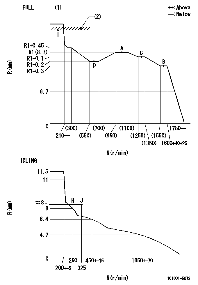
N:Pump speed
R:Rack position (mm)
(1)Torque cam stamping: T1
(2)RACK LIMIT
----------
T1=93
----------
----------
T1=93
----------
Speed control lever angle
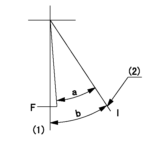
F:Full speed
I:Idle
(1)-
(2)Stopper bolt setting
----------
----------
a=32.5deg+-3deg b=34deg+-5deg
----------
----------
a=32.5deg+-3deg b=34deg+-5deg
Stop lever angle

N:Pump normal
S:Stop the pump.
----------
----------
a=40deg+-5deg b=40deg+-5deg
----------
----------
a=40deg+-5deg b=40deg+-5deg
0000001501 ACTUATOR
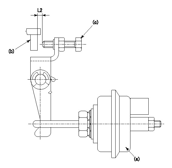
(a) actuator
(b) Speed lever
(c) set bolt
(d) control lever
1. Actuator adjustment procedure
(1)Apply negative pressure P1 to the actuator (a) and confirm that the stroke is approximately L1.
(2)Set the speed lever (b) at the idling position (N = 0).
(3)Set temporarily so that the clearance from the set bolt is approximately L2.
(4)Set the pump speed at N1 and apply negative pressure P2.
(5)Adjust set bolt (c) so that the rack position is R1 to R2.
(6)Set the pump speed at N2 and apply negative pressure P3.
(7)At this time, confirm that the speed lever (b) moves smoothly and that the rack position becomes R1 to R2.
----------
L1=10mm L2=2mm P1=66.7kPa(500mmHg) P2=66.7kPa(500mmHg) P3=66.7kPa(500mmHg) N1=250r/min N2=250r/min R1=8.4mm R2=8.7mm
----------
----------
L1=10mm L2=2mm P1=66.7kPa(500mmHg) P2=66.7kPa(500mmHg) P3=66.7kPa(500mmHg) N1=250r/min N2=250r/min R1=8.4mm R2=8.7mm
----------
Timing setting

(1)Pump vertical direction
(2)Position of gear's standard threaded hole at No 1 cylinder's beginning of injection
(3)-
(4)-
----------
----------
a=(70deg)
----------
----------
a=(70deg)
Information:
Fuel consumption complaints are related to engine owners expectations. They may often times be related to the engine itself, causes other than the engine, and in some cases the fuel consumption may be normal for the application. Only a good discussion with the owner/operator, as described in the "Owner/Operator Input" section, will give guidance as to a correct repair or to prevent unnecessary repairs.Owner/Operator Input
The following are some of the questions which should be asked before beginning any diagnosis or repair for an engine performance complaint. There Are No Hard And Fast Answers For These Questions. There are many factors that can cause poor fuel mileage or make users believe they are getting fuel-poor-mileage.There are also a variety of customer expectations which are acceptable. The answers to these questions will give you a better understanding and perspective on the complaint and may identify characteristics which will help pinpoint the cause of the complaint quickly. 1. Are miles measured accurately?A most common problem in determining mpg is errors in recording the number of miles traveled. A. Is this vehicle hub or cab odometer accurate?The easiest way to check an odometer is to install a hub odometer known to be accurate and for the tire size on the truck. Run the truck over several hundred miles and compare the reading with the original odometer.Odometers may also be checked by comparing them to interstate mile posts or by running over a course of known length - a 50-mile run is required to get a good check. B. Are "book miles" or "driver-paid miles" correct?Another way in which miles for mpg calculations are obtained by a fleet is the use of "book miles" or "driver-paid miles". The use of this system can short mileage accumulation by 10 to 15%; thus, mpg is low by 10 to 15%. C. Is the vehicle used for pick-up and delivery operation?Another problem affecting mileage accumulation in many fleets is the use of linehaul equipment for pickup and delivery operations. In the "book mile" system, the truck rarely gets credit for any miles run in pick-up and delivery. 2. Is fuel measurement accurate?There are a number of ways in which fuel measurement can be the source of mpg problems. A. Are fuel pumps calibrated?If fuel tickets come from company-owned fuel pumps, there can be errors because nonrevenue fuel pumps do not have calibration requirements in many states. B. Are road fuel tickets accurate?The only way to verify fuel additions when road fuel tickets are used is a laborious ticket-by-ticket audit ensuring that the correct amount of fuel has been entered for the vehicles in question and that there are no indications of incorrect entries. C. Are tank-full mileage checks correctly done?The big problem in "tank-full" checks is getting the tank filled to the same level before and after the user "checked the mileage". With two 100 gallon tanks, errors of 5 to 10 gallons are very common in topping off tanks because of the way truck tanks
The following are some of the questions which should be asked before beginning any diagnosis or repair for an engine performance complaint. There Are No Hard And Fast Answers For These Questions. There are many factors that can cause poor fuel mileage or make users believe they are getting fuel-poor-mileage.There are also a variety of customer expectations which are acceptable. The answers to these questions will give you a better understanding and perspective on the complaint and may identify characteristics which will help pinpoint the cause of the complaint quickly. 1. Are miles measured accurately?A most common problem in determining mpg is errors in recording the number of miles traveled. A. Is this vehicle hub or cab odometer accurate?The easiest way to check an odometer is to install a hub odometer known to be accurate and for the tire size on the truck. Run the truck over several hundred miles and compare the reading with the original odometer.Odometers may also be checked by comparing them to interstate mile posts or by running over a course of known length - a 50-mile run is required to get a good check. B. Are "book miles" or "driver-paid miles" correct?Another way in which miles for mpg calculations are obtained by a fleet is the use of "book miles" or "driver-paid miles". The use of this system can short mileage accumulation by 10 to 15%; thus, mpg is low by 10 to 15%. C. Is the vehicle used for pick-up and delivery operation?Another problem affecting mileage accumulation in many fleets is the use of linehaul equipment for pickup and delivery operations. In the "book mile" system, the truck rarely gets credit for any miles run in pick-up and delivery. 2. Is fuel measurement accurate?There are a number of ways in which fuel measurement can be the source of mpg problems. A. Are fuel pumps calibrated?If fuel tickets come from company-owned fuel pumps, there can be errors because nonrevenue fuel pumps do not have calibration requirements in many states. B. Are road fuel tickets accurate?The only way to verify fuel additions when road fuel tickets are used is a laborious ticket-by-ticket audit ensuring that the correct amount of fuel has been entered for the vehicles in question and that there are no indications of incorrect entries. C. Are tank-full mileage checks correctly done?The big problem in "tank-full" checks is getting the tank filled to the same level before and after the user "checked the mileage". With two 100 gallon tanks, errors of 5 to 10 gallons are very common in topping off tanks because of the way truck tanks
Have questions with 101601-5073?
Group cross 101601-5073 ZEXEL
Hino
Hino
Hino
Hino
Hino
Hino
Hino
101601-5073
9 400 614 598
220801321A
INJECTION-PUMP ASSEMBLY
W06D
W06D