Information injection-pump assembly
ZEXEL
101601-5070
1016015070
HINO
220801320A
220801320a

Rating:
Cross reference number
ZEXEL
101601-5070
1016015070
HINO
220801320A
220801320a
Zexel num
Bosch num
Firm num
Name
Calibration Data:
Adjustment conditions
Test oil
1404 Test oil ISO4113 or {SAEJ967d}
1404 Test oil ISO4113 or {SAEJ967d}
Test oil temperature
degC
40
40
45
Nozzle and nozzle holder
105780-8140
Bosch type code
EF8511/9A
Nozzle
105780-0000
Bosch type code
DN12SD12T
Nozzle holder
105780-2080
Bosch type code
EF8511/9
Opening pressure
MPa
17.2
Opening pressure
kgf/cm2
175
Injection pipe
Outer diameter - inner diameter - length (mm) mm 6-2-600
Outer diameter - inner diameter - length (mm) mm 6-2-600
Overflow valve
131424-5720
Overflow valve opening pressure
kPa
255
221
289
Overflow valve opening pressure
kgf/cm2
2.6
2.25
2.95
Tester oil delivery pressure
kPa
157
157
157
Tester oil delivery pressure
kgf/cm2
1.6
1.6
1.6
Direction of rotation (viewed from drive side)
Right R
Right R
Injection timing adjustment
Direction of rotation (viewed from drive side)
Right R
Right R
Injection order
1-4-2-6-
3-5
Pre-stroke
mm
3.1
3.07
3.13
Beginning of injection position
Drive side NO.1
Drive side NO.1
Difference between angles 1
Cal 1-4 deg. 60 59.75 60.25
Cal 1-4 deg. 60 59.75 60.25
Difference between angles 2
Cyl.1-2 deg. 120 119.75 120.25
Cyl.1-2 deg. 120 119.75 120.25
Difference between angles 3
Cal 1-6 deg. 180 179.75 180.25
Cal 1-6 deg. 180 179.75 180.25
Difference between angles 4
Cal 1-3 deg. 240 239.75 240.25
Cal 1-3 deg. 240 239.75 240.25
Difference between angles 5
Cal 1-5 deg. 300 299.75 300.25
Cal 1-5 deg. 300 299.75 300.25
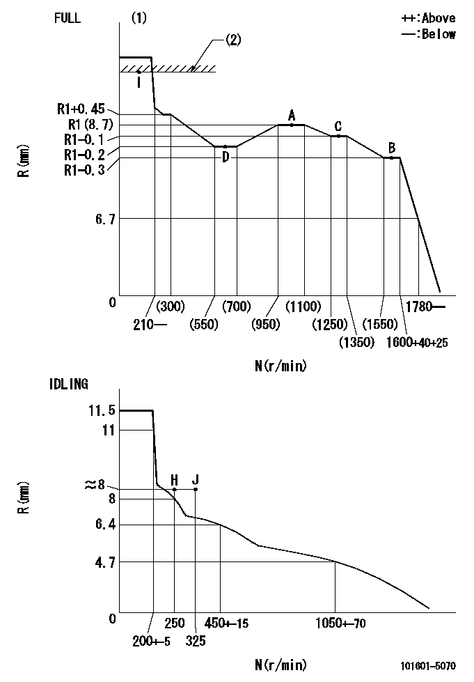
Injection quantity adjustment
Adjusting point
-
Rack position
8.7
Pump speed
r/min
1000
1000
1000
Average injection quantity
mm3/st.
44.4
42.4
46.4
Max. variation between cylinders
%
0
-3
3
Basic
*
Fixing the rack
*
Standard for adjustment of the maximum variation between cylinders
*
Injection quantity adjustment_02
Adjusting point
H
Rack position
8+-0.5
Pump speed
r/min
250
250
250
Average injection quantity
mm3/st.
8
6.5
9.5
Max. variation between cylinders
%
0
-15
15
Fixing the rack
*
Standard for adjustment of the maximum variation between cylinders
*
Injection quantity adjustment_03
Adjusting point
A
Rack position
R1(8.7)
Pump speed
r/min
1000
1000
1000
Average injection quantity
mm3/st.
44.4
43.4
45.4
Basic
*
Fixing the lever
*
Injection quantity adjustment_04
Adjusting point
B
Rack position
R1-0.3
Pump speed
r/min
1600
1600
1600
Average injection quantity
mm3/st.
43.5
41.5
45.5
Fixing the lever
*
Injection quantity adjustment_05
Adjusting point
C
Rack position
R1-0.1
Pump speed
r/min
1300
1300
1300
Average injection quantity
mm3/st.
44.1
42.1
46.1
Fixing the lever
*
Injection quantity adjustment_06
Adjusting point
D
Rack position
R1-0.2
Pump speed
r/min
650
650
650
Average injection quantity
mm3/st.
36.2
34.2
38.2
Fixing the lever
*
Injection quantity adjustment_07
Adjusting point
I
Rack position
13.5+-0.
5
Pump speed
r/min
100
100
100
Average injection quantity
mm3/st.
95
95
105
Fixing the lever
*
Rack limit
*
Timer adjustment
Pump speed
r/min
1300+50
Advance angle
deg.
0
0
0
Remarks
Start
Start
Timer adjustment_02
Pump speed
r/min
1600
Advance angle
deg.
5
4.7
5.3
Remarks
Finish
Finish
Test data Ex:
Governor adjustment
N:Pump speed
R:Rack position (mm)
(1)Torque cam stamping: T1
(2)RACK LIMIT
----------
T1=93
----------
----------
T1=93
----------
Speed control lever angle
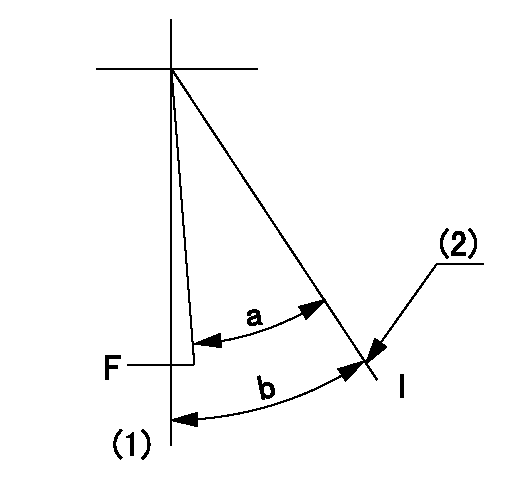
F:Full speed
I:Idle
(1)-
(2)Stopper bolt setting
----------
----------
a=32.5deg+-3deg b=34deg+-5deg
----------
----------
a=32.5deg+-3deg b=34deg+-5deg
Stop lever angle

N:Pump normal
S:Stop the pump.
----------
----------
a=40deg+-5deg b=40deg+-5deg
----------
----------
a=40deg+-5deg b=40deg+-5deg
0000001501 ACTUATOR
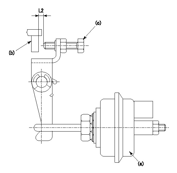
(a) actuator
(b) Speed lever
(c) set bolt
(d) control lever
1. Actuator adjustment procedure
(1)Apply negative pressure P1 to the actuator (a) and confirm that the stroke is approximately L1.
(2)Set the speed lever (b) at the idling position (N = 0).
(3)Set temporarily so that the clearance from the set bolt is approximately L2.
(4)Set the pump speed at N1 and apply negative pressure P2.
(5)Adjust set bolt (c) so that the rack position is R1 to R2.
(6)Set the pump speed at N2 and apply negative pressure P3.
(7)At this time, confirm that the speed lever (b) moves smoothly and that the rack position becomes R1 to R2.
----------
L1=10mm L2=2mm P1=66.7kPa(500mmHg) P2=66.7kPa(500mmHg) P3=66.7kPa(500mmHg) N1=250r/min N2=250r/min R1=8.4mm R2=8.7mm
----------
----------
L1=10mm L2=2mm P1=66.7kPa(500mmHg) P2=66.7kPa(500mmHg) P3=66.7kPa(500mmHg) N1=250r/min N2=250r/min R1=8.4mm R2=8.7mm
----------
Timing setting

(1)Pump vertical direction
(2)Position of gear's standard threaded hole at No 1 cylinder's beginning of injection
(3)-
(4)-
----------
----------
a=(70deg)
----------
----------
a=(70deg)
Information:
Starting Motor
The starting motor is used to turn the engine flywheel fast enough to get the engine to start running.The starting motor has a solenoid. When the start switch is activated, the solenoid will move the starting motor pinion to engage it with the ring gear on the flywheel of the engine. The starting motor pinion will engage with the ring gear before the electric contacts in the solenoid close the circuit between the battery and the starting motor. When the circuit between the battery and the starting motor is complete, the pinion will turn the engine flywheel. A clutch gives protection for the starting motor so that the engine cannot turn the starting motor too fast. When the start switch is released, the starting motor pinion will move away from the ring gear.
Starting Motor Cross Section
(1) Field. (2) Solenoid. (3) Clutch. (4) Pinion. (5) Commutator. (6) Brush assembly. (7) Armature.Other Components
Circuit Breaker
Circuit Breaker Schematic
(1) Reset button. (2) Disc in open position. (3) Contacts. (4) Disc. (5) Battery circuit terminals.The circuit breaker is a switch that opens the battery circuit if the current in the electrical system goes higher than the rating of the circuit breaker.A heat activated metal disc with a contact point makes complete the electric circuit through the circuit breaker. If the current in the electrical system gets too high, it causes the metal disc to get hot. This heat causes a distortion of the metal disc which opens the contacts and breaks the circuit. A circuit breaker that is open can be reset (an adjustment to make the circuit complete again) after it becomes cool. Push the reset button to close the contacts and reset the circuit breaker.Compression Brake
The compression brake permits the operator to control the speed of the vehicle on grades, curves, or anytime when speed reduction is necessary, but long applications of the service brakes are not desired. In downhill operation, or any slow down condition, the engine crankshaft is turned by the rear wheels (through the differential, driveshaft, transmission and clutch). To reduce the speed of the vehicle, an application of a braking force can be made to the pistons of the engine.The compression brake, when activated, does this through the conversion of the engine from a source of power to an air compressor that absorbs (takes) power. This conversion is made possible by a master to slave piston arrangement, where movement of the rocker arm for the exhaust valve of one cylinder is transferred hydraulically to open the exhaust valve of another cylinder near the top of its normal compression stroke cycle. The compressed cylinder charge is now released into the exhaust manifold.The release of the compressed air pressure to the atmosphere prevents the return of energy to the engine piston on the expansion (power) stroke. The result is an energy loss, since the work done by the compression of the cylinder charge is not returned by the expansion process. This energy loss is taken from the rear wheels,