Information injection-pump assembly
ZEXEL
101601-5050
1016015050
HINO
220004720A
220004720a

Rating:
Cross reference number
ZEXEL
101601-5050
1016015050
HINO
220004720A
220004720a
Zexel num
Bosch num
Firm num
Name
Calibration Data:
Adjustment conditions
Test oil
1404 Test oil ISO4113 or {SAEJ967d}
1404 Test oil ISO4113 or {SAEJ967d}
Test oil temperature
degC
40
40
45
Nozzle and nozzle holder
105780-8140
Bosch type code
EF8511/9A
Nozzle
105780-0000
Bosch type code
DN12SD12T
Nozzle holder
105780-2080
Bosch type code
EF8511/9
Opening pressure
MPa
17.2
Opening pressure
kgf/cm2
175
Injection pipe
Outer diameter - inner diameter - length (mm) mm 6-2-600
Outer diameter - inner diameter - length (mm) mm 6-2-600
Overflow valve
131424-5720
Overflow valve opening pressure
kPa
255
221
289
Overflow valve opening pressure
kgf/cm2
2.6
2.25
2.95
Tester oil delivery pressure
kPa
157
157
157
Tester oil delivery pressure
kgf/cm2
1.6
1.6
1.6
Direction of rotation (viewed from drive side)
Right R
Right R
Injection timing adjustment
Direction of rotation (viewed from drive side)
Right R
Right R
Injection order
1-4-2-6-
3-5
Pre-stroke
mm
3.1
3.07
3.13
Beginning of injection position
Drive side NO.1
Drive side NO.1
Difference between angles 1
Cal 1-4 deg. 60 59.75 60.25
Cal 1-4 deg. 60 59.75 60.25
Difference between angles 2
Cyl.1-2 deg. 120 119.75 120.25
Cyl.1-2 deg. 120 119.75 120.25
Difference between angles 3
Cal 1-6 deg. 180 179.75 180.25
Cal 1-6 deg. 180 179.75 180.25
Difference between angles 4
Cal 1-3 deg. 240 239.75 240.25
Cal 1-3 deg. 240 239.75 240.25
Difference between angles 5
Cal 1-5 deg. 300 299.75 300.25
Cal 1-5 deg. 300 299.75 300.25
Injection quantity adjustment
Adjusting point
-
Rack position
8.7
Pump speed
r/min
1000
1000
1000
Average injection quantity
mm3/st.
44.4
42.4
46.4
Max. variation between cylinders
%
0
-3
3
Basic
*
Fixing the rack
*
Standard for adjustment of the maximum variation between cylinders
*
Injection quantity adjustment_02
Adjusting point
H
Rack position
8+-0.5
Pump speed
r/min
250
250
250
Average injection quantity
mm3/st.
8
6.5
9.5
Max. variation between cylinders
%
0
-15
15
Fixing the rack
*
Standard for adjustment of the maximum variation between cylinders
*
Injection quantity adjustment_03
Adjusting point
A
Rack position
R1(8.7)
Pump speed
r/min
1000
1000
1000
Average injection quantity
mm3/st.
44.4
43.4
45.4
Basic
*
Fixing the lever
*
Injection quantity adjustment_04
Adjusting point
B
Rack position
R1-0.3
Pump speed
r/min
1600
1600
1600
Average injection quantity
mm3/st.
43.5
41.5
45.5
Fixing the lever
*
Injection quantity adjustment_05
Adjusting point
C
Rack position
R1-0.1
Pump speed
r/min
1300
1300
1300
Average injection quantity
mm3/st.
44.1
42.1
46.1
Fixing the lever
*
Injection quantity adjustment_06
Adjusting point
D
Rack position
R1-0.2
Pump speed
r/min
650
650
650
Average injection quantity
mm3/st.
36.2
34.2
38.2
Fixing the lever
*
Injection quantity adjustment_07
Adjusting point
I
Rack position
13.5+-0.
5
Pump speed
r/min
100
100
100
Average injection quantity
mm3/st.
95
95
105
Fixing the lever
*
Rack limit
*
Timer adjustment
Pump speed
r/min
1300+50
Advance angle
deg.
0
0
0
Remarks
Start
Start
Timer adjustment_02
Pump speed
r/min
1600
Advance angle
deg.
5
4.7
5.3
Remarks
Finish
Finish
Test data Ex:
Governor adjustment
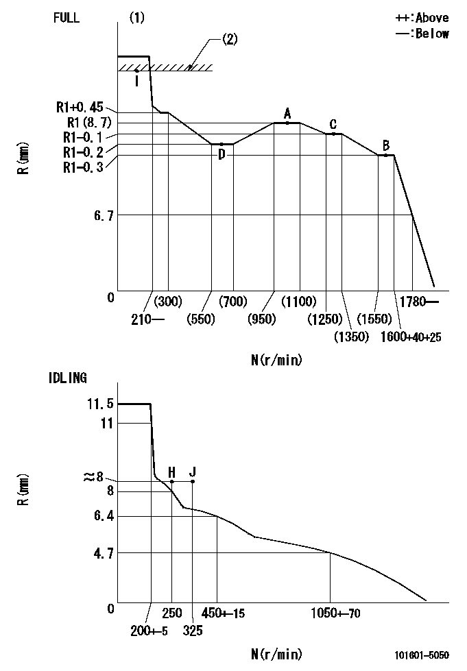
N:Pump speed
R:Rack position (mm)
(1)Torque cam stamping: T1
(2)RACK LIMIT
----------
T1=93
----------
----------
T1=93
----------
Speed control lever angle
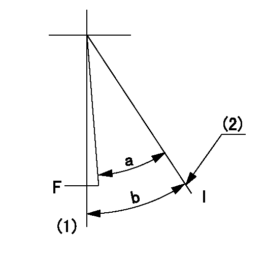
F:Full speed
I:Idle
(1)-
(2)Stopper bolt setting
----------
----------
a=32.5deg+-3deg b=34deg+-5deg
----------
----------
a=32.5deg+-3deg b=34deg+-5deg
Stop lever angle

N:Pump normal
S:Stop the pump.
----------
----------
a=40deg+-5deg b=40deg+-5deg
----------
----------
a=40deg+-5deg b=40deg+-5deg
Timing setting

(1)Pump vertical direction
(2)Position of gear's standard threaded hole at No 1 cylinder's beginning of injection
(3)-
(4)-
----------
----------
a=(70deg)
----------
----------
a=(70deg)
Information:
Start By:a. remove cylinder headb. remove oil panc. remove oil pumpd. remove cooling tubes 1. Check the connecting rods and caps for their identification and location.2. Remove rod cap nuts (1) and cap (2) from connecting rod (3). Remove the lower half of bearing (4) from cap (2).
To protect the crankshaft from the threaded portion of connecting rod bolts (5), cut a short piece of rubber hose and install it over both rod bolts (5).
3. Remove the piston and connecting rod, then remove the upper half of rod bearing (4). The following steps are for the installation of the pistons and connecting rod assemblies.4. Put clean oil on piston rings, connecting rod bearings and cylinder bore.5. Position the piston ring end gaps 120° apart and install tooling (A).6. Put the short pieces of hose over the threaded portion of rod bolts (5), to protect crankshaft.7. With number one crankshaft throw at bottom center, install the piston and connecting rod. Engines which use one piece pistons have the word "FRONT" stamped on the crown of the piston. Make sure the word "FRONT" is toward the front of the engine when the piston is installed.8. Taking care to line up connecting rod and crankshaft, carefully tap piston into cylinder bore until tooling (A) comes off the piston. 9. Before connecting rod (3) comes in contact with the crankshaft, install upper half of rod bearing (4). Be sure the bearing tab engages the groove in the connecting rod.10. Put engine oil on upper rod bearing surface, then tap piston down, guiding connecting rod onto crankshaft.11. Position lower half of rod bearing (4) in corresponding numbered rod cap (2). Be sure the bearing tab engages the grove in the rod caps.12. Put engine oil on the lower rod bearing surface, then install the rod cap. Install the bearing cap on the connecting rod with the number on the bearing (rod) cap on the same side and same number as on the connecting rod.13. Put engine oil on the threads of bolts (5). Install rod cap nuts (1) and tighten them to a torque of 54 7 N m (40 5 lb.ft.).14. Put an alignment mark on cap and nut. Then, tighten each nut an additional 60° 5° (1/6 turn).15. Repeat the steps for the remainder of the pistons and connecting rods.End By:a. install cooling tubesb. install oil pumpc. install oil pand. install cylinder headDisassemble And Assemble Pistons And Connecting Rods
Start By:a. remove pistons and connecting rods 1. Remove snap ring (1) remove piston pin (2). Separate piston (3) and connecting rod (4).
One Piece Piston
Two Piece Piston2. Use tooling (A) and remove piston rings (5). The following steps are for the assembly of the pistons and connecting rods.3. Check the clearance between the ends of the piston rings (5). See the topic, Pistons And Rings in the Specifications section of the service manual. The oil ring is to be installed over the spring with the end gap 180° from the