Information injection-pump assembly
ZEXEL
101601-5032
1016015032
HINO
220004711A
220004711a
Rating:
Service parts 101601-5032 INJECTION-PUMP ASSEMBLY:
1.
_
6.
COUPLING PLATE
7.
COUPLING PLATE
8.
_
9.
_
11.
Nozzle and Holder
12.
Open Pre:MPa(Kqf/cm2)
21.6(220)

15.
NOZZLE SET
Cross reference number
ZEXEL
101601-5032
1016015032
HINO
220004711A
220004711a
Zexel num
Bosch num
Firm num
Name
101601-5032
220004711A HINO
INJECTION-PUMP ASSEMBLY
W06D * K
W06D * K
Calibration Data:
Adjustment conditions
Test oil
1404 Test oil ISO4113 or {SAEJ967d}
1404 Test oil ISO4113 or {SAEJ967d}
Test oil temperature
degC
40
40
45
Nozzle and nozzle holder
105780-8140
Bosch type code
EF8511/9A
Nozzle
105780-0000
Bosch type code
DN12SD12T
Nozzle holder
105780-2080
Bosch type code
EF8511/9
Opening pressure
MPa
17.2
Opening pressure
kgf/cm2
175
Injection pipe
Outer diameter - inner diameter - length (mm) mm 6-2-600
Outer diameter - inner diameter - length (mm) mm 6-2-600
Overflow valve
131424-5720
Overflow valve opening pressure
kPa
255
221
289
Overflow valve opening pressure
kgf/cm2
2.6
2.25
2.95
Tester oil delivery pressure
kPa
157
157
157
Tester oil delivery pressure
kgf/cm2
1.6
1.6
1.6
Direction of rotation (viewed from drive side)
Right R
Right R
Injection timing adjustment
Direction of rotation (viewed from drive side)
Right R
Right R
Injection order
1-4-2-6-
3-5
Pre-stroke
mm
3.1
3.07
3.13
Beginning of injection position
Drive side NO.1
Drive side NO.1
Difference between angles 1
Cal 1-4 deg. 60 59.75 60.25
Cal 1-4 deg. 60 59.75 60.25
Difference between angles 2
Cyl.1-2 deg. 120 119.75 120.25
Cyl.1-2 deg. 120 119.75 120.25
Difference between angles 3
Cal 1-6 deg. 180 179.75 180.25
Cal 1-6 deg. 180 179.75 180.25
Difference between angles 4
Cal 1-3 deg. 240 239.75 240.25
Cal 1-3 deg. 240 239.75 240.25
Difference between angles 5
Cal 1-5 deg. 300 299.75 300.25
Cal 1-5 deg. 300 299.75 300.25
Injection quantity adjustment
Adjusting point
-
Rack position
8.8
Pump speed
r/min
1000
1000
1000
Average injection quantity
mm3/st.
49.2
47.2
51.2
Max. variation between cylinders
%
0
-3.5
3.5
Basic
*
Fixing the rack
*
Standard for adjustment of the maximum variation between cylinders
*
Injection quantity adjustment_02
Adjusting point
H
Rack position
8+-0.5
Pump speed
r/min
250
250
250
Average injection quantity
mm3/st.
8
6.5
9.5
Max. variation between cylinders
%
0
-10
10
Fixing the rack
*
Standard for adjustment of the maximum variation between cylinders
*
Injection quantity adjustment_03
Adjusting point
A
Rack position
R1(8.8)
Pump speed
r/min
1000
1000
1000
Average injection quantity
mm3/st.
49.2
48.2
50.2
Basic
*
Fixing the lever
*
Injection quantity adjustment_04
Adjusting point
B
Rack position
R1-0.35
Pump speed
r/min
1600
1600
1600
Average injection quantity
mm3/st.
45
43
47
Fixing the lever
*
Injection quantity adjustment_05
Adjusting point
C
Rack position
R1+0.2
Pump speed
r/min
1300
1300
1300
Average injection quantity
mm3/st.
55.7
53.7
57.7
Fixing the lever
*
Injection quantity adjustment_06
Adjusting point
D
Rack position
R1-0.15
Pump speed
r/min
650
650
650
Average injection quantity
mm3/st.
38.7
36.7
40.7
Fixing the lever
*
Injection quantity adjustment_07
Adjusting point
I
Rack position
13.5+-0.
5
Pump speed
r/min
100
100
100
Average injection quantity
mm3/st.
95
95
105
Fixing the lever
*
Rack limit
*
Timer adjustment
Pump speed
r/min
1300+50
Advance angle
deg.
0
0
0
Remarks
Start
Start
Timer adjustment_02
Pump speed
r/min
1600
Advance angle
deg.
5
4.7
5.3
Remarks
Finish
Finish
Test data Ex:
Governor adjustment
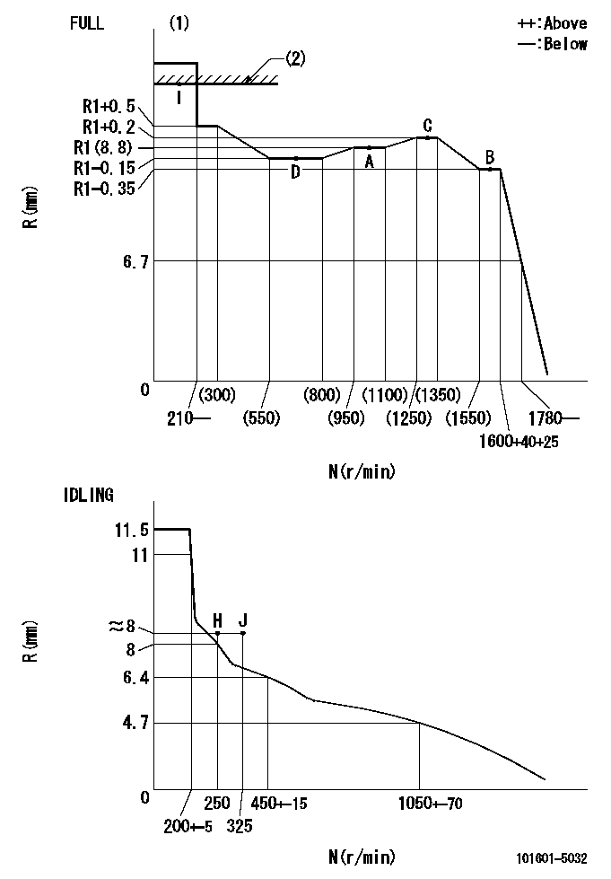
N:Pump speed
R:Rack position (mm)
(1)Torque cam stamping: T1
(2)RACK LIMIT
----------
T1=90
----------
----------
T1=90
----------
Speed control lever angle

F:Full speed
I:Idle
(1)Stopper bolt set position 'H'
----------
----------
a=33deg+-3deg b=34deg+-5deg
----------
----------
a=33deg+-3deg b=34deg+-5deg
Stop lever angle

N:Pump normal
S:Stop the pump.
----------
----------
a=40deg+-5deg b=40deg+-5deg
----------
----------
a=40deg+-5deg b=40deg+-5deg
Timing setting

(1)Pump vertical direction
(2)Position of gear's standard threaded hole at No 1 cylinder's beginning of injection
(3)-
(4)-
----------
----------
a=(70deg)
----------
----------
a=(70deg)
Information:
1. Disconnect oil supply line (1) and oil drain tube (2). Remove the four mounting nuts and remove the turbocharger. Remove the gasket. The following steps are for the installation of the turbocharger.2. Apply 5P3931 Anti-Seize to turbocharger mounting studs. Position turbocharger gasket and turbocharger, then Install the four mounting nuts. Tighten the four mounting nuts to a torque of 54 5 N m (40 4 lb.ft.).3. Position gaskets and install drain tube (2) and supply line (1).Disassemble And Assemble Turbocharger
Start By:a. remove turbocharger 1. Remove bolts (1) and (2). Remove the compressor and turbine housings.2. Remove nut (3) and compressor wheel (4). Slide out turbine wheel (5) and shaft.3. Remove adapter plate snap ring (6).4. Use two screwdrivers and remove adapter plate (7).5. Remove bushings (8), spacers (9), and seals (10).6. Remove snap ring (11) and bushing (12).7. Remove snap ring (13) and bushing (14). The following steps are for the assembly of the turbocharger.8. Install bushing (12) and snap ring (11). Repeat for bushing (14) and snap ring (13).9. With th seals and shield (15) in place, install shaft and turbine wheel assembly (5).10. Install the spacers, bushings, plate, seals and adapter plate. Install the snap ring (not illustrated).
Do not allow any of the 7M7456 Locktite to get on the shaft. Damage to the turbocharger may occur.
11. Install compressor wheel (4) on the shaft. Put one drop of 7M7456 Locktite on the threads and install nut (3). Tighten nut (3) to a torque of 15.6 .7 N m (138 6 lb.in.).12. Position the turbine and compressor housings. Put 5P3931 Anti-Seize Compound on the bolts and install. Tighten bolts (1) for the compressor cover to a torque of 7.3 .6 N m (65 5 lb.in.). Tighten bolts (2), for the turbine housing to a torque of 15.8 .6 N m (140 5 lb.in.).End by:a. Install turbocharger
Have questions with 101601-5032?
Group cross 101601-5032 ZEXEL
Hino
Hino
Hino
101601-5032
220004711A
INJECTION-PUMP ASSEMBLY
W06D
W06D