Information injection-pump assembly
ZEXEL
101601-5031
1016015031
Rating:
Service parts 101601-5031 INJECTION-PUMP ASSEMBLY:
1.
_
6.
COUPLING PLATE
7.
COUPLING PLATE
8.
_
9.
_
11.
Nozzle and Holder
12.
Open Pre:MPa(Kqf/cm2)
21.6(220)

15.
NOZZLE SET
Cross reference number
ZEXEL
101601-5031
1016015031
Zexel num
Bosch num
Firm num
Name
101601-5031
INJECTION-PUMP ASSEMBLY
Calibration Data:
Adjustment conditions
Test oil
1404 Test oil ISO4113 or {SAEJ967d}
1404 Test oil ISO4113 or {SAEJ967d}
Test oil temperature
degC
40
40
45
Nozzle and nozzle holder
105780-8140
Bosch type code
EF8511/9A
Nozzle
105780-0000
Bosch type code
DN12SD12T
Nozzle holder
105780-2080
Bosch type code
EF8511/9
Opening pressure
MPa
17.2
Opening pressure
kgf/cm2
175
Injection pipe
Outer diameter - inner diameter - length (mm) mm 6-2-600
Outer diameter - inner diameter - length (mm) mm 6-2-600
Overflow valve
131424-5720
Overflow valve opening pressure
kPa
255
221
289
Overflow valve opening pressure
kgf/cm2
2.6
2.25
2.95
Tester oil delivery pressure
kPa
157
157
157
Tester oil delivery pressure
kgf/cm2
1.6
1.6
1.6
Direction of rotation (viewed from drive side)
Right R
Right R
Injection timing adjustment
Direction of rotation (viewed from drive side)
Right R
Right R
Injection order
1-4-2-6-
3-5
Pre-stroke
mm
3.1
3.07
3.13
Beginning of injection position
Drive side NO.1
Drive side NO.1
Difference between angles 1
Cal 1-4 deg. 60 59.75 60.25
Cal 1-4 deg. 60 59.75 60.25
Difference between angles 2
Cyl.1-2 deg. 120 119.75 120.25
Cyl.1-2 deg. 120 119.75 120.25
Difference between angles 3
Cal 1-6 deg. 180 179.75 180.25
Cal 1-6 deg. 180 179.75 180.25
Difference between angles 4
Cal 1-3 deg. 240 239.75 240.25
Cal 1-3 deg. 240 239.75 240.25
Difference between angles 5
Cal 1-5 deg. 300 299.75 300.25
Cal 1-5 deg. 300 299.75 300.25
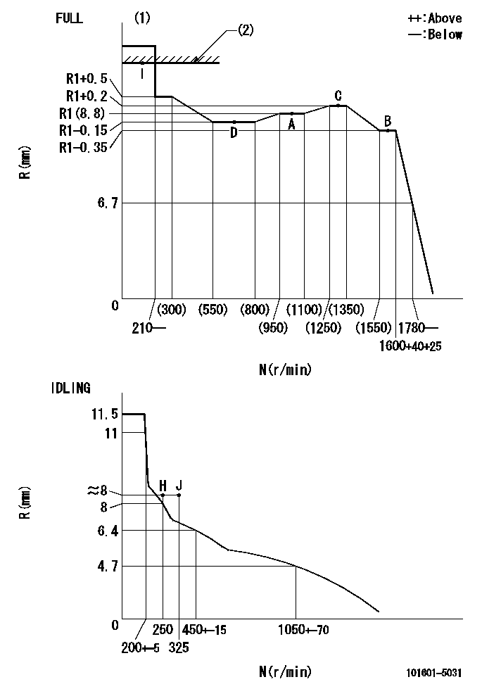
Injection quantity adjustment
Adjusting point
-
Rack position
8.8
Pump speed
r/min
1000
1000
1000
Average injection quantity
mm3/st.
49.2
47.2
51.2
Max. variation between cylinders
%
0
-3.5
3.5
Basic
*
Fixing the rack
*
Standard for adjustment of the maximum variation between cylinders
*
Injection quantity adjustment_02
Adjusting point
H
Rack position
8+-0.5
Pump speed
r/min
250
250
250
Average injection quantity
mm3/st.
8
6.5
9.5
Max. variation between cylinders
%
0
-10
10
Fixing the rack
*
Standard for adjustment of the maximum variation between cylinders
*
Injection quantity adjustment_03
Adjusting point
A
Rack position
R1(8.8)
Pump speed
r/min
1000
1000
1000
Average injection quantity
mm3/st.
49.2
48.2
50.2
Basic
*
Fixing the lever
*
Injection quantity adjustment_04
Adjusting point
B
Rack position
R1-0.35
Pump speed
r/min
1600
1600
1600
Average injection quantity
mm3/st.
45
43
47
Fixing the lever
*
Injection quantity adjustment_05
Adjusting point
C
Rack position
R1+0.2
Pump speed
r/min
1300
1300
1300
Average injection quantity
mm3/st.
55.7
53.7
57.7
Fixing the lever
*
Injection quantity adjustment_06
Adjusting point
D
Rack position
R1-0.15
Pump speed
r/min
650
650
650
Average injection quantity
mm3/st.
38.7
36.7
40.7
Fixing the lever
*
Injection quantity adjustment_07
Adjusting point
I
Rack position
13.5+-0.
5
Pump speed
r/min
100
100
100
Average injection quantity
mm3/st.
95
95
105
Fixing the lever
*
Rack limit
*
Timer adjustment
Pump speed
r/min
1300+50
Advance angle
deg.
0
0
0
Remarks
Start
Start
Timer adjustment_02
Pump speed
r/min
1600
Advance angle
deg.
5
4.7
5.3
Remarks
Finish
Finish
Test data Ex:
Governor adjustment
N:Pump speed
R:Rack position (mm)
(1)Torque cam stamping: T1
(2)RACK LIMIT
----------
T1=90
----------
----------
T1=90
----------
Speed control lever angle

F:Full speed
I:Idle
(1)Stopper bolt set position 'H'
----------
----------
a=33deg+-3deg b=34deg+-5deg
----------
----------
a=33deg+-3deg b=34deg+-5deg
Stop lever angle

N:Pump normal
S:Stop the pump.
----------
----------
a=40deg+-5deg b=40deg+-5deg
----------
----------
a=40deg+-5deg b=40deg+-5deg
Timing setting

(1)Pump vertical direction
(2)Position of gear's standard threaded hole at No 1 cylinder's beginning of injection
(3)-
(4)-
----------
----------
a=(70deg)
----------
----------
a=(70deg)
Information:
Start By:a. remove shutoff solenoidb. remove governorc. remove governor spring groupd. remove rear cover group 1. Remove riser (1). 2. Remove retaining ring (2), races (3) with bearing (4) and shims (5). 3. Remove four flyweight bolts (6) with washers.4. Remove flyweights (7), toe (8) and pins (9). Keep parts of each flyweight group together.5. Remove pin (9). Inspect for wear.6. Remove flyweight toe (8). Inspect for wear.7. Inspect flyweight pin bore for wear. Replace any flyweight parts with wear.8. Hold flyweight carrier (10) to keep from rotating, and remove eight carrier bolts (11). Replace, do not reuse, eight carrier bolts (11),9. Remove flyweight carrier (10), riser shaft (12) and the drive pin.10. Remove fuel transfer pump (13) and the fittings. See the topic, Remove Fuel Transfer Pump.11. Remove two bolts (14) and remove shutoff assembly (15). 12. If necessary, remove levers (16), (17) and remove spring (18). These components are part of the shutoff assembly service replacement. Do not disassemble shutoff assembly beyond this point. 13. Remove throttle spring (23), setscrew (19), spring (20) and lever (21).14. Remove retaining ring (22) and pull throttle shaft assembly (24) out of the housing bore. Do not disassemble throttle shaft assembly beyond this point.15. If necessary, remove the throttle shaft seal.16. Remove governor front housing from Repair Stand, and turn it over. If not previously removed, remove the housing o-ring seal. 17. Remove drive gear bolt (25) and lift cover (26) from the gear drive unit.
Be careful not to damage the "C" spring, by over compressing with the vise.
18. Use a vise to remove "C" (27). Remove gear assembly (28). Do not disassemble the gear beyond this point
Do not attempt to remove the gear carrier, it is serviced as part of the housing assembly.
The following steps are for the assembly of the front housing.19. Position gear (28) onto carrier (29). Assemble with short length, 8.43 mm (.332 in.), of dowel pin in gear assembly, face down (toward housing). Be sure gear rotates freely on carrier bore.
Be careful not to damage the "C" spring, by over compressing with the vise.
20. Install "C" spring (27). Be sure that there is preload when assembled. Orient cover so the dowel, which is pressed into carrier (29), fits into the hole in the cover. The dowel from the gear assembly fits into the slot in the cover.21. Install cover (26) and bolt (25).22. Mount front housing to repair stand.23. If the throttle shaft seal was removed, install it with the lip toward the inside of the governor.24. Install throttle shaft (24) into housing bore, and install retaining ring (22).25. Slide lever (21) and spring (20) onto throttle shaft. The long leg of spring (20) fits into slot on lever (21). The other end of spring (20) fits into slot on the throttle shaft.26. Install throttle spring (23). These parts must be oriented correctly for proper governor operation. Following is a quick check for proper assembly.27. With zero preload on spring, the threaded hole in throttle
Be careful not to damage the "C" spring, by over compressing with the vise.
18. Use a vise to remove "C" (27). Remove gear assembly (28). Do not disassemble the gear beyond this point
Do not attempt to remove the gear carrier, it is serviced as part of the housing assembly.
The following steps are for the assembly of the front housing.19. Position gear (28) onto carrier (29). Assemble with short length, 8.43 mm (.332 in.), of dowel pin in gear assembly, face down (toward housing). Be sure gear rotates freely on carrier bore.
Be careful not to damage the "C" spring, by over compressing with the vise.
20. Install "C" spring (27). Be sure that there is preload when assembled. Orient cover so the dowel, which is pressed into carrier (29), fits into the hole in the cover. The dowel from the gear assembly fits into the slot in the cover.21. Install cover (26) and bolt (25).22. Mount front housing to repair stand.23. If the throttle shaft seal was removed, install it with the lip toward the inside of the governor.24. Install throttle shaft (24) into housing bore, and install retaining ring (22).25. Slide lever (21) and spring (20) onto throttle shaft. The long leg of spring (20) fits into slot on lever (21). The other end of spring (20) fits into slot on the throttle shaft.26. Install throttle spring (23). These parts must be oriented correctly for proper governor operation. Following is a quick check for proper assembly.27. With zero preload on spring, the threaded hole in throttle
Have questions with 101601-5031?
Group cross 101601-5031 ZEXEL
Hino
Hino
101601-5031
INJECTION-PUMP ASSEMBLY