Information injection-pump assembly
ZEXEL
101601-5022
1016015022
HINO
220004701B
220004701b
Rating:
Service parts 101601-5022 INJECTION-PUMP ASSEMBLY:
1.
_
6.
COUPLING PLATE
7.
COUPLING PLATE
8.
_
9.
_
11.
Nozzle and Holder
12.
Open Pre:MPa(Kqf/cm2)
21.6(220)

15.
NOZZLE SET
Cross reference number
ZEXEL
101601-5022
1016015022
HINO
220004701B
220004701b
Zexel num
Bosch num
Firm num
Name
101601-5022
220004701B HINO
INJECTION-PUMP ASSEMBLY
W06D * K
W06D * K
Calibration Data:
Adjustment conditions
Test oil
1404 Test oil ISO4113 or {SAEJ967d}
1404 Test oil ISO4113 or {SAEJ967d}
Test oil temperature
degC
40
40
45
Nozzle and nozzle holder
105780-8140
Bosch type code
EF8511/9A
Nozzle
105780-0000
Bosch type code
DN12SD12T
Nozzle holder
105780-2080
Bosch type code
EF8511/9
Opening pressure
MPa
17.2
Opening pressure
kgf/cm2
175
Injection pipe
Outer diameter - inner diameter - length (mm) mm 6-2-600
Outer diameter - inner diameter - length (mm) mm 6-2-600
Overflow valve
131424-5720
Overflow valve opening pressure
kPa
255
221
289
Overflow valve opening pressure
kgf/cm2
2.6
2.25
2.95
Tester oil delivery pressure
kPa
157
157
157
Tester oil delivery pressure
kgf/cm2
1.6
1.6
1.6
Direction of rotation (viewed from drive side)
Right R
Right R
Injection timing adjustment
Direction of rotation (viewed from drive side)
Right R
Right R
Injection order
1-4-2-6-
3-5
Pre-stroke
mm
3.1
3.07
3.13
Beginning of injection position
Drive side NO.1
Drive side NO.1
Difference between angles 1
Cal 1-4 deg. 60 59.75 60.25
Cal 1-4 deg. 60 59.75 60.25
Difference between angles 2
Cyl.1-2 deg. 120 119.75 120.25
Cyl.1-2 deg. 120 119.75 120.25
Difference between angles 3
Cal 1-6 deg. 180 179.75 180.25
Cal 1-6 deg. 180 179.75 180.25
Difference between angles 4
Cal 1-3 deg. 240 239.75 240.25
Cal 1-3 deg. 240 239.75 240.25
Difference between angles 5
Cal 1-5 deg. 300 299.75 300.25
Cal 1-5 deg. 300 299.75 300.25
Injection quantity adjustment
Adjusting point
-
Rack position
8.7
Pump speed
r/min
1000
1000
1000
Average injection quantity
mm3/st.
46.6
44.6
48.6
Max. variation between cylinders
%
0
-3.5
3.5
Basic
*
Fixing the rack
*
Standard for adjustment of the maximum variation between cylinders
*
Injection quantity adjustment_02
Adjusting point
H
Rack position
8+-0.5
Pump speed
r/min
250
250
250
Average injection quantity
mm3/st.
8
6.5
9.5
Max. variation between cylinders
%
0
-10
10
Fixing the rack
*
Standard for adjustment of the maximum variation between cylinders
*
Injection quantity adjustment_03
Adjusting point
A
Rack position
R1(8.7)
Pump speed
r/min
1000
1000
1000
Average injection quantity
mm3/st.
46.6
45.6
47.6
Basic
*
Fixing the lever
*
Injection quantity adjustment_04
Adjusting point
B
Rack position
R1-0.3
Pump speed
r/min
1600
1600
1600
Average injection quantity
mm3/st.
45.2
43.2
47.2
Fixing the lever
*
Injection quantity adjustment_05
Adjusting point
C
Rack position
R1+0.2
Pump speed
r/min
1300
1300
1300
Average injection quantity
mm3/st.
52
50
54
Fixing the lever
*
Injection quantity adjustment_06
Adjusting point
D
Rack position
R1-0.15
Pump speed
r/min
650
650
650
Average injection quantity
mm3/st.
38
36
40
Fixing the lever
*
Injection quantity adjustment_07
Adjusting point
I
Rack position
13.5+-0.
5
Pump speed
r/min
100
100
100
Average injection quantity
mm3/st.
95
95
105
Fixing the lever
*
Rack limit
*
Injection quantity adjustment_08
Adjusting point
E
Rack position
R1+0.35
Pump speed
r/min
400
400
400
Average injection quantity
mm3/st.
28
24
32
Fixing the lever
*
Timer adjustment
Pump speed
r/min
1300+50
Advance angle
deg.
0
0
0
Remarks
Start
Start
Timer adjustment_02
Pump speed
r/min
1600
Advance angle
deg.
3.5
3.2
3.8
Remarks
Finish
Finish
Test data Ex:
Governor adjustment
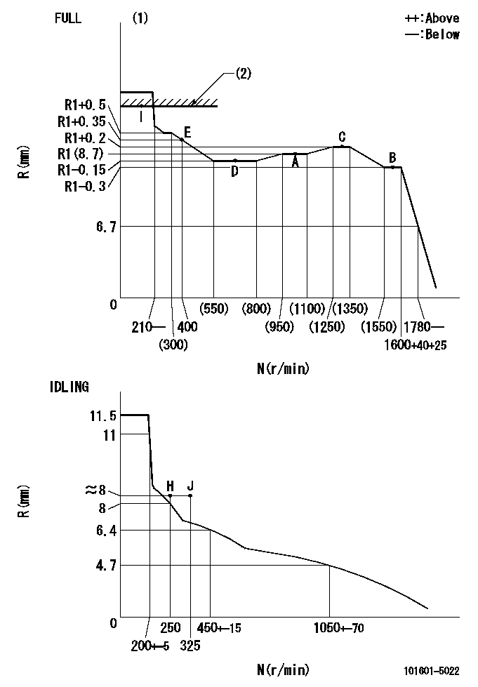
N:Pump speed
R:Rack position (mm)
(1)Torque cam stamping: T1
(2)RACK LIMIT
----------
T1=A76
----------
----------
T1=A76
----------
Speed control lever angle

F:Full speed
I:Idle
(1)Stopper bolt set position 'H'
----------
----------
a=33deg+-3deg b=34deg+-5deg
----------
----------
a=33deg+-3deg b=34deg+-5deg
Stop lever angle

N:Pump normal
S:Stop the pump.
----------
----------
a=40deg+-5deg b=40deg+-5deg
----------
----------
a=40deg+-5deg b=40deg+-5deg
Timing setting

(1)Pump vertical direction
(2)Position of gear's standard threaded hole at No 1 cylinder's beginning of injection
(3)-
(4)-
----------
----------
a=(70deg)
----------
----------
a=(70deg)
Information:
T-T-T Procedure
A torque-turn-tighten (T-T-T) procedure is used in many specifications and instructions.1. Clean the bolt and nut threads.2. Put lubrication of the threads and the seat face of the bolt and nut.3. Turn the bolt or the nut tight according to the torque specification.4. Put a location mark on the part and on the bolt head or nut.5. Turn the bolt or the nut tighter the amount of degrees according to the specifications The side of a nut or bolt head can be used for reference if a mark can not be put on. Torque Wrench Extension
When a torque wrench extension is used with a torque wrench, the torque indication on the torque wrench will be less than the real torque.
(E) Torque wrench drive axis-to-torque wrench extension drive axis. (W) Mark on handle-to-torque wrench drive axis.1. Put a mark on the handle. Measure the handle from the mark to the axis of the torque wrench drive (W).2. Measure the torque wrench extension from the torque wrench drive to the axis of the torque wrench extension drive (E).3. To get correct torque indication (TI) when the real torque (RT) is known: Example: W = 304.8 mm (12 in); E = 65.0 mm (2.56 in); RT (from specifications) = 17 N m (125 lb ft). 4. Hold the torque wrench handle with the longest finger of the hand over the mark on the handle to get the real torque (RT) with low torque indication (TI) on the torque wrench.Locks
Flat metal locks must be installed properly to be effective. Bend one end of the lock around the edge of the part. Bend the other end against one flat surface of the nut of bolt head.Always install new locks in components which house moving parts.If lockwashers are installed on housings made of aluminum, use a flat washer between the lockwasher and the housing. Lines And Wires
When removing or disconnecting a group of lines or wires, tag each one to assure proper assembly.Lubrication
Where applicable, fill the compartments of the components serviced with the amount, type and grade of lubricant recommended in the Operation Maintenance Manual.Rust Preventive Compound
Clean the rust preventive compound from all machined surfaces of new parts before installing the part.Shims
When shims are removed, tie them together and identify them as to location. Keep shims clean and flat until they are reinstalled.Bearings
Anti-Friction Bearings
When an anti-friction bearing is removed, cover it to keep out dirt and abrasives. Wash the bearings in nonflammable cleaning solution and allow them to drain dry. The bearings may be dried with compressed air, but DO NOT SPIN THE BEARING. Discard the bearings if the races and balls or rollers are pitted, scored or burned. If the bearing is serviceable, coat it with oil and wrap it in clean paper. DO NOT unwrap new bearings until time of installation.The life of an anti-friction bearing will be shortened if not properly lubricated.Double Row, Tapered Roller
Double row, tapered roller bearings are precision fit during manufacture and the components are not interchangeable.
Have questions with 101601-5022?
Group cross 101601-5022 ZEXEL
Hino
Hino
101601-5022
220004701B
INJECTION-PUMP ASSEMBLY
W06D
W06D