Information injection-pump assembly
BOSCH
9 400 619 717
9400619717
ZEXEL
101601-5013
1016015013
Rating:
Service parts 101601-5013 INJECTION-PUMP ASSEMBLY:
1.
_
6.
COUPLING PLATE
7.
COUPLING PLATE
8.
_
9.
_
11.
Nozzle and Holder
12.
Open Pre:MPa(Kqf/cm2)
21.6{220}
15.
NOZZLE SET
Cross reference number
BOSCH
9 400 619 717
9400619717
ZEXEL
101601-5013
1016015013
Zexel num
Bosch num
Firm num
Name
Calibration Data:
Adjustment conditions
Test oil
1404 Test oil ISO4113 or {SAEJ967d}
1404 Test oil ISO4113 or {SAEJ967d}
Test oil temperature
degC
40
40
45
Nozzle and nozzle holder
105780-8140
Bosch type code
EF8511/9A
Nozzle
105780-0000
Bosch type code
DN12SD12T
Nozzle holder
105780-2080
Bosch type code
EF8511/9
Opening pressure
MPa
17.2
Opening pressure
kgf/cm2
175
Injection pipe
Outer diameter - inner diameter - length (mm) mm 6-2-600
Outer diameter - inner diameter - length (mm) mm 6-2-600
Overflow valve
131424-5720
Overflow valve opening pressure
kPa
255
221
289
Overflow valve opening pressure
kgf/cm2
2.6
2.25
2.95
Tester oil delivery pressure
kPa
157
157
157
Tester oil delivery pressure
kgf/cm2
1.6
1.6
1.6
Direction of rotation (viewed from drive side)
Right R
Right R
Injection timing adjustment
Direction of rotation (viewed from drive side)
Right R
Right R
Injection order
1-4-2-6-
3-5
Pre-stroke
mm
3.1
3.07
3.13
Beginning of injection position
Drive side NO.1
Drive side NO.1
Difference between angles 1
Cal 1-4 deg. 60 59.75 60.25
Cal 1-4 deg. 60 59.75 60.25
Difference between angles 2
Cyl.1-2 deg. 120 119.75 120.25
Cyl.1-2 deg. 120 119.75 120.25
Difference between angles 3
Cal 1-6 deg. 180 179.75 180.25
Cal 1-6 deg. 180 179.75 180.25
Difference between angles 4
Cal 1-3 deg. 240 239.75 240.25
Cal 1-3 deg. 240 239.75 240.25
Difference between angles 5
Cal 1-5 deg. 300 299.75 300.25
Cal 1-5 deg. 300 299.75 300.25
Injection quantity adjustment
Adjusting point
-
Rack position
9.3
Pump speed
r/min
1000
1000
1000
Average injection quantity
mm3/st.
61.9
59.9
63.9
Max. variation between cylinders
%
0
-3.5
3.5
Basic
*
Fixing the rack
*
Standard for adjustment of the maximum variation between cylinders
*
Injection quantity adjustment_02
Adjusting point
-
Rack position
8.4+-0.5
Pump speed
r/min
250
250
250
Average injection quantity
mm3/st.
9
7.5
10.5
Max. variation between cylinders
%
0
-10
10
Fixing the rack
*
Standard for adjustment of the maximum variation between cylinders
*
Remarks
Adjust only variation between cylinders; adjust governor according to governor specifications.
Adjust only variation between cylinders; adjust governor according to governor specifications.
Injection quantity adjustment_03
Adjusting point
A
Rack position
R1(9.3)
Pump speed
r/min
1000
1000
1000
Average injection quantity
mm3/st.
61.9
60.9
62.9
Basic
*
Fixing the lever
*
Injection quantity adjustment_04
Adjusting point
B
Rack position
R1-0.3
Pump speed
r/min
1600
1600
1600
Average injection quantity
mm3/st.
59.9
57.9
61.9
Fixing the lever
*
Injection quantity adjustment_05
Adjusting point
D
Rack position
R1+0.1
Pump speed
r/min
1300
1300
1300
Average injection quantity
mm3/st.
66.3
64.3
68.3
Fixing the lever
*
Injection quantity adjustment_06
Adjusting point
C
Rack position
R1-0.5
Pump speed
r/min
650
650
650
Average injection quantity
mm3/st.
40.5
38.5
42.5
Fixing the lever
*
Injection quantity adjustment_07
Adjusting point
E
Rack position
R1-0.1
Pump speed
r/min
400
400
400
Average injection quantity
mm3/st.
29.7
27.7
31.7
Fixing the lever
*
Injection quantity adjustment_08
Adjusting point
I
Rack position
-
Pump speed
r/min
100
100
100
Average injection quantity
mm3/st.
99
99
109
Fixing the lever
*
Rack limit
*
Timer adjustment
Pump speed
r/min
1050--
Advance angle
deg.
0
0
0
Remarks
Start
Start
Timer adjustment_02
Pump speed
r/min
1000
Advance angle
deg.
0.3
Timer adjustment_03
Pump speed
r/min
1500
Advance angle
deg.
3.5
3.2
3.8
Remarks
Finish
Finish
Test data Ex:
Governor adjustment
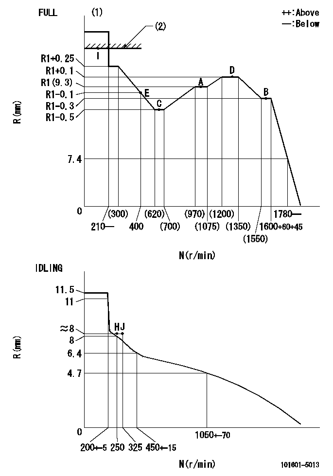
N:Pump speed
R:Rack position (mm)
(1)Torque cam stamping: T1
(2)RACK LIMIT
----------
T1=B57
----------
----------
T1=B57
----------
Speed control lever angle

F:Full speed
I:Idle
(1)Stopper bolt set position 'H'
----------
----------
a=(34deg)+-3deg b=34deg+-5deg
----------
----------
a=(34deg)+-3deg b=34deg+-5deg
Stop lever angle

N:Pump normal
S:Stop the pump.
----------
----------
a=40deg+-5deg b=40deg+-5deg
----------
----------
a=40deg+-5deg b=40deg+-5deg
Timing setting

(1)Pump vertical direction
(2)Position of gear's standard threaded hole at No 1 cylinder's beginning of injection
(3)-
(4)-
----------
----------
a=(70deg)
----------
----------
a=(70deg)
Information:
(1) Body assembly. Install piston with "FRONT" toward front of engine. Assemble so the markings "FRONT" on the piston body assembly and the forging part number on the connecting rod assembly point in opposite directions. Install connecting rod and piston group with rod forging part number to the rear of the engine. The rear of the engine is the flywheel end. Thoroughly lubricate the piston group with clean engine oil just before inserting into block group.(2) Connecting rod.Top And Intermediate Ring
Install piston ring with "UP" side toward top of piston.(3) Top Ring has the mark "UP-1". Clearance between ends of piston ring when installed in a cylinder with a bore size of 105.025 mm (4.1348 in) ... 0.525 0.125 mm (.021 .005 in)Increase in clearance between ends of piston ring for each 0.03 mm (.001 in) increase in cylinder bore size ... 0.09 mm (.004 in)(4) Intermediate Ring has the
Install piston ring with "UP" side toward top of piston.(3) Top Ring has the mark "UP-1". Clearance between ends of piston ring when installed in a cylinder with a bore size of 105.025 mm (4.1348 in) ... 0.525 0.125 mm (.021 .005 in)Increase in clearance between ends of piston ring for each 0.03 mm (.001 in) increase in cylinder bore size ... 0.09 mm (.004 in)(4) Intermediate Ring has the