Information injection-pump assembly
ZEXEL
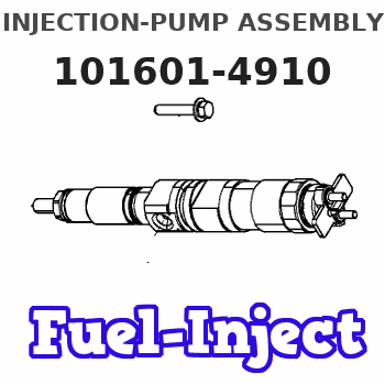
101601-4910
1016014910
ISUZU
1156008391
1156008391
Rating:
Cross reference number
ZEXEL
101601-4910
1016014910
ISUZU
1156008391
1156008391
Zexel num
Bosch num
Firm num
Name
101601-4910
1156008391 ISUZU
INJECTION-PUMP ASSEMBLY
6BB1 * K
6BB1 * K
Calibration Data:
Adjustment conditions
Test oil
1404 Test oil ISO4113 or {SAEJ967d}
1404 Test oil ISO4113 or {SAEJ967d}
Test oil temperature
degC
40
40
45
Nozzle and nozzle holder
105780-8140
Bosch type code
EF8511/9A
Nozzle
105780-0000
Bosch type code
DN12SD12T
Nozzle holder
105780-2080
Bosch type code
EF8511/9
Opening pressure
MPa
17.2
Opening pressure
kgf/cm2
175
Injection pipe
Outer diameter - inner diameter - length (mm) mm 6-2-600
Outer diameter - inner diameter - length (mm) mm 6-2-600
Overflow valve
132424-0620
Overflow valve opening pressure
kPa
157
123
191
Overflow valve opening pressure
kgf/cm2
1.6
1.25
1.95
Tester oil delivery pressure
kPa
157
157
157
Tester oil delivery pressure
kgf/cm2
1.6
1.6
1.6
Direction of rotation (viewed from drive side)
Right R
Right R
Injection timing adjustment
Direction of rotation (viewed from drive side)
Right R
Right R
Injection order
1-5-3-6-
2-4
Pre-stroke
mm
2.4
2.35
2.45
Rack position
Point B R=B
Point B R=B
Beginning of injection position
Drive side NO.1
Drive side NO.1
Difference between angles 1
Cal 1-5 deg. 60 59.5 60.5
Cal 1-5 deg. 60 59.5 60.5
Difference between angles 2
Cal 1-3 deg. 120 119.5 120.5
Cal 1-3 deg. 120 119.5 120.5
Difference between angles 3
Cal 1-6 deg. 180 179.5 180.5
Cal 1-6 deg. 180 179.5 180.5
Difference between angles 4
Cyl.1-2 deg. 240 239.5 240.5
Cyl.1-2 deg. 240 239.5 240.5
Difference between angles 5
Cal 1-4 deg. 300 299.5 300.5
Cal 1-4 deg. 300 299.5 300.5
Injection quantity adjustment
Adjusting point
A
Rack position
8.3
Pump speed
r/min
1650
1650
1650
Average injection quantity
mm3/st.
43
40.6
45.4
Max. variation between cylinders
%
0
-4
4
Fixing the lever
*
Injection quantity adjustment_02
Adjusting point
B
Rack position
8.3
Pump speed
r/min
1000
1000
1000
Average injection quantity
mm3/st.
42.5
40.1
44.9
Max. variation between cylinders
%
0
-2.5
2.5
Basic
*
Fixing the lever
*
Injection quantity adjustment_03
Adjusting point
C
Rack position
6.9+-0.5
Pump speed
r/min
325
325
325
Average injection quantity
mm3/st.
9.4
8.1
10.7
Max. variation between cylinders
%
0
-14
14
Fixing the rack
*
Remarks
Adjust only variation between cylinders; adjust governor according to governor specifications.
Adjust only variation between cylinders; adjust governor according to governor specifications.
Injection quantity adjustment_04
Adjusting point
D
Rack position
-
Pump speed
r/min
100
100
100
Average injection quantity
mm3/st.
60.5
60.5
Fixing the lever
*
Remarks
After startup boost setting
After startup boost setting
Timer adjustment
Pump speed
r/min
1000
Advance angle
deg.
0.5
Timer adjustment_02
Pump speed
r/min
1200
Advance angle
deg.
0.8
0.3
1.3
Timer adjustment_03
Pump speed
r/min
1450
Advance angle
deg.
2
1.5
2.5
Timer adjustment_04
Pump speed
r/min
1650
Advance angle
deg.
3
2.5
3.5
Timer adjustment_05
Pump speed
r/min
-
Advance angle
deg.
5
5
5
Remarks
Measure the actual speed, stop
Measure the actual speed, stop
Test data Ex:
Governor adjustment
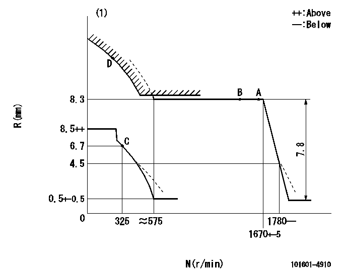
N:Pump speed
R:Rack position (mm)
(1)Beginning of damper spring operation: DL
----------
DL=5.2-0.2mm
----------
----------
DL=5.2-0.2mm
----------
0000000901
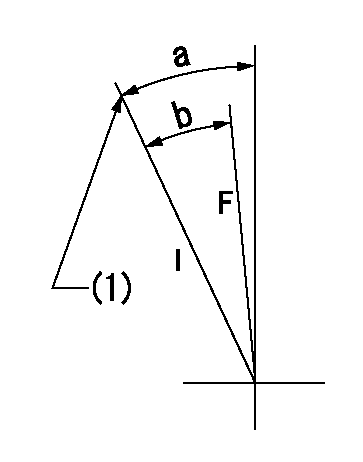
F:Full load
I:Idle
(1)Stopper bolt setting
----------
----------
a=(33deg)+-5deg b=(26deg)+-3deg
----------
----------
a=(33deg)+-5deg b=(26deg)+-3deg
Timing setting

(1)Pump vertical direction
(2)Position of gear mark 'CC' at No 1 cylinder's beginning of injection
(3)B.T.D.C.: aa
(4)-
----------
aa=18deg
----------
a=(90deg)
----------
aa=18deg
----------
a=(90deg)
Information:
Start By:a. remove timing gear cover 1. Remove bolt (1) and washer that fastens the weight assembly (2).
Weight assembly must have support during removal to prevent damage to components.
2. Install tooling (A) and remove the weight assembly.Install Automatic Timing Advance Unit
1. Install washer and bolt (1). With the fuel pump housing cover removed, turn the fuel pump camshaft in the direction of engine rotation until tool (A) can be installed in the notch of the camshaft. 2. To time the fuel injection pump to the engine with the front timing cover removed, follow Steps 3 and 4. With the timing cover installed, see Steps 6 and 7. No. 1 piston at top center (TC) on the compression stroke is the starting point for all timing procedures. The engine is seen from the flywheel end when direction of crankshaft rotation is given.3. Turn the crankshaft counterclockwise until the "C" on the crankshaft and camshaft and camshaft gears are in alignment. 4. Remove the plug and install tool (B) in the flywheel housing.5. To find top center compression stroke for No. 1 piston, turn the flywheel clockwise (opposite of engine rotation) approximately 30°. This procedure is to remove all end play from timing gears.6. Turn the flywheel counterclockwise (direction of engine rotation) until tool (B) can be installed in the flywheel. The piston is at top center. If you go past the bolt hole you must start over again. To see if the No. 1 piston is on the compression stroke, remove the breather assembly from the valve cover and look at the valves of the No. 1 cylinder. The valves will be closed if No. 1 cylinder is on the compression stroke. You must be able to move the rocker arms up and down with your hand.7. If NO. 1 piston is not on the compression stroke, remove tooling (B) and turn the flywheel 360° counterclockwise. Install tooling (B). The No. 1 piston is now at top center on the compression stroke.8. With tooling (A) and (B) installed in position, install the timing advance weight assembly on the fuel pump camshaft. 9. Install tooling (C) on the weight assembly. While a constant torque on drive gear on 68 N m (50 lb ft) is held, tighten the bolt that fastens the weight assembly to fuel pump camshaft to a torque of 270 25 N m (200 18 lb ft).10. Remove tooling (A), (B) and (C).End By:a. install timing gear coverDisassemble And Assemble Automatic Timing Unit
Start By:a. remove automatic timing advance unit
Keep all parts clean from contaminants. Contaminants put into the system may cause rapid wear and shortened component life.
1. Remove two screws (1) and plate (2).
The weights are held on position with two springs for each weight under compression. Carefully remove weights and springs to prevent possible injury.
2. Remove springs (4) and (5), weight (3) and slide (6) from each side of assembly. 3. If necessary, remove gear (7). Remove seals (11) and (10). The following steps
Have questions with 101601-4910?
Group cross 101601-4910 ZEXEL
Isuzu
101601-4910
1156008391
INJECTION-PUMP ASSEMBLY
6BB1
6BB1