Information injection-pump assembly
ZEXEL
101601-3190
1016013190
KOMATSU
6138721560
6138721560

Rating:
Service parts 101601-3190 INJECTION-PUMP ASSEMBLY:
1.
_
7.
COUPLING PLATE
8.
_
9.
_
11.
Nozzle and Holder
12.
Open Pre:MPa(Kqf/cm2)
24.5(250)
15.
NOZZLE SET
Cross reference number
ZEXEL
101601-3190
1016013190
KOMATSU
6138721560
6138721560
Zexel num
Bosch num
Firm num
Name
101601-3190
6138721560 KOMATSU
INJECTION-PUMP ASSEMBLY
S6D110 * K
S6D110 * K
Calibration Data:
Adjustment conditions
Test oil
1404 Test oil ISO4113 or {SAEJ967d}
1404 Test oil ISO4113 or {SAEJ967d}
Test oil temperature
degC
40
40
45
Nozzle and nozzle holder
105780-8140
Bosch type code
EF8511/9A
Nozzle
105780-0000
Bosch type code
DN12SD12T
Nozzle holder
105780-2080
Bosch type code
EF8511/9
Opening pressure
MPa
17.2
Opening pressure
kgf/cm2
175
Injection pipe
Outer diameter - inner diameter - length (mm) mm 6-2-600
Outer diameter - inner diameter - length (mm) mm 6-2-600
Tester oil delivery pressure
kPa
157
157
157
Tester oil delivery pressure
kgf/cm2
1.6
1.6
1.6
Direction of rotation (viewed from drive side)
Right R
Right R
Injection timing adjustment
Direction of rotation (viewed from drive side)
Right R
Right R
Injection order
1-5-3-6-
2-4
Pre-stroke
mm
4
3.95
4.05
Beginning of injection position
Drive side NO.1
Drive side NO.1
Difference between angles 1
Cal 1-5 deg. 60 59.5 60.5
Cal 1-5 deg. 60 59.5 60.5
Difference between angles 2
Cal 1-3 deg. 120 119.5 120.5
Cal 1-3 deg. 120 119.5 120.5
Difference between angles 3
Cal 1-6 deg. 180 179.5 180.5
Cal 1-6 deg. 180 179.5 180.5
Difference between angles 4
Cyl.1-2 deg. 240 239.5 240.5
Cyl.1-2 deg. 240 239.5 240.5
Difference between angles 5
Cal 1-4 deg. 300 299.5 300.5
Cal 1-4 deg. 300 299.5 300.5
Injection quantity adjustment
Adjusting point
A
Rack position
10.5
Pump speed
r/min
1100
1100
1100
Average injection quantity
mm3/st.
82
81
83
Max. variation between cylinders
%
0
-2
2
Basic
*
Fixing the lever
*
Injection quantity adjustment_02
Adjusting point
B
Rack position
7.4+-0.5
Pump speed
r/min
400
400
400
Average injection quantity
mm3/st.
12.5
11.3
13.7
Max. variation between cylinders
%
0
-10
10
Fixing the rack
*
Timer adjustment
Pump speed
r/min
750--
Advance angle
deg.
0
0
0
Remarks
Start
Start
Timer adjustment_02
Pump speed
r/min
700
Advance angle
deg.
0.5
Timer adjustment_03
Pump speed
r/min
900
Advance angle
deg.
1.4
0.9
1.9
Timer adjustment_04
Pump speed
r/min
1100
Advance angle
deg.
3
2.5
3.5
Timer adjustment_05
Pump speed
r/min
-
Advance angle
deg.
3.5
3.5
3.5
Remarks
Measure the actual speed, stop
Measure the actual speed, stop
Test data Ex:
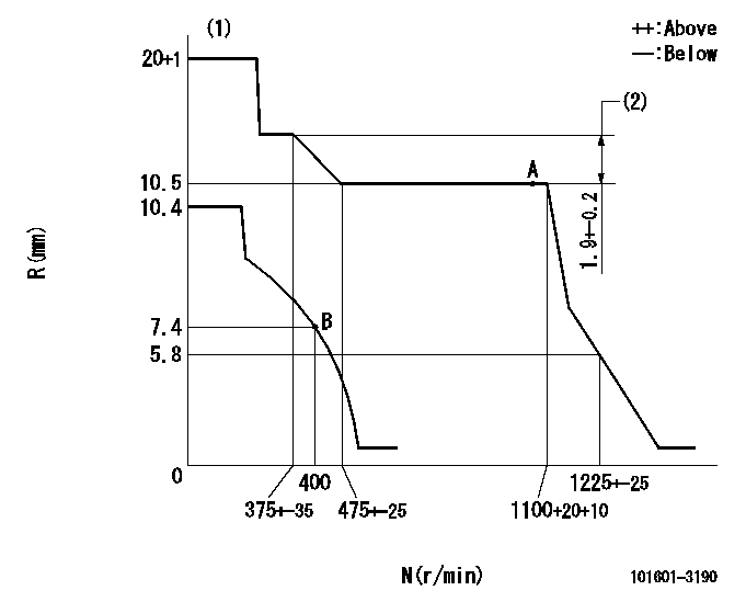
Governor adjustment

N:Pump speed
R:Rack position (mm)
(1)Target notch: K
(2)Rack difference between N = N1 and N = N2
----------
K=11 N1=1100r/min N2=330r/min
----------
----------
K=11 N1=1100r/min N2=330r/min
----------
Speed control lever angle

F:Full speed
I:Idle
(1)Stopper bolt setting
----------
----------
a=2deg+-5deg b=18deg+-5deg
----------
----------
a=2deg+-5deg b=18deg+-5deg
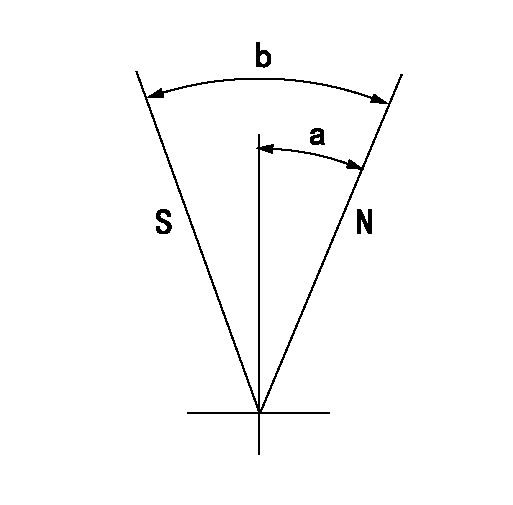
Stop lever angle

N:Pump normal
S:Stop the pump.
----------
----------
a=27deg+-5deg b=53deg+-5deg
----------
----------
a=27deg+-5deg b=53deg+-5deg
Timing setting

(1)Pump vertical direction
(2)Coupling's key groove position at No 1 cylinder's beginning of injection
(3)-
(4)-
----------
----------
a=(0deg)
----------
----------
a=(0deg)
Information:
Illustration 8 g01455580
(6) 294-3395 Exhaust Support Assembly
Make four mounting holes for 294-3395 Exhaust Support Assembly (6) in the location (designated with a circle) which is shown in Illustration 8.
Illustration 9 g01456256
(17) 8T-4223 Hard Washers (18) 8T-4244 Nuts (19) 8T-4648 Bolt (20) 8T-4956 Bolt (21) 8T-6868 Bolts
Install exhaust support assembly (6) by using two 8T-6868 Bolts (21), one 8T-4648 Bolt (19), one 8T-4956 Bolt (20), four 8T-4223 Hard Washers (17), and four 8T-4244 Nuts (18). Refer to Illustration 9.
Illustration 10 g01456263
(9) 295-3044 Exhaust Support Groups (Lower half)
Remove the upper clamp from each 295-3044 Exhaust Support Group (9) by removing the two bolts and two hard washers. Keep the four bolts, the four hard washers, and the two upper clamps together. These parts will be reinstalled in Step 15.
Use four 8T-4956 Bolts (20) and four 8T-4223 Hard Washers (17) to install both 295-3044 Exhaust Support Groups (9) to exhaust support assembly (6). Refer to Illustration 10.
Illustration 11 g01456281
(5) 294-3065 Diesel Particulate Filter Group
To facilitate handling, remove the filter units from 294-3065 Diesel Particulate Filter Group (5) by removing the two clamps (including gaskets) closest to the rectangular intake manifold. Place the filter units, clamps, and gaskets aside.Note: Handle the removed filter units with extra care, as the internal structure is subject to damage due to impact, dropping, etc. Do not allow the inside of the filter units to get wet.
Install 294-3065 Diesel Particulate Filter Group (5) by aligning the mounting holes in the intake manifold with the mounting holes in the welded exhaust support assembly (7). Secure the intake manifold to the exhaust support assembly by using two 8T-4956 Bolts (20), two 8T-4223 Hard Washers (17), and two 8T-4244 Nuts (18). Refer to Illustration 11.
Reattach the lower filter unit to the intake manifold by reinstalling the clamp and the gasket that was removed in Step 12. Repeat for the upper filter unit.
Illustration 12 g01456285
Align the mounting holes in the upper half of 295-3044 Exhaust Support Group (9) with the mounting holes in the lower half of the exhaust support group (9). Reinstall the two bolts (9a) and the two hard washers (9b). Repeat for the other exhaust support group (9). Refer to Illustration 12.
Connect the straight end of exhaust tube assembly (8) to the manifold inlet pipe of the Diesel Particulate Filter Group. Use one 190-5341 Clamp (3)
Have questions with 101601-3190?
Group cross 101601-3190 ZEXEL
Komatsu
101601-3190
6138721560
INJECTION-PUMP ASSEMBLY
S6D110
S6D110