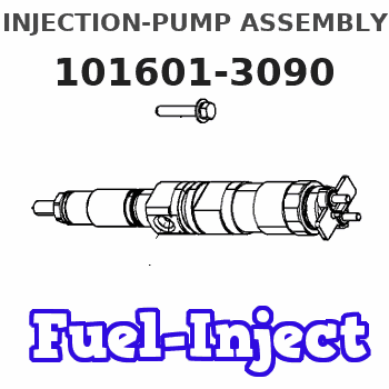
Information injection-pump assembly
ZEXEL
101601-3090
1016013090
Rating:
Cross reference number
ZEXEL
101601-3090
1016013090
Zexel num
Bosch num
Firm num
Name
Calibration Data:
Adjustment conditions
Test oil
1404 Test oil ISO4113 or {SAEJ967d}
1404 Test oil ISO4113 or {SAEJ967d}
Test oil temperature
degC
40
40
45
Nozzle and nozzle holder
105780-8140
Bosch type code
EF8511/9A
Nozzle
105780-0000
Bosch type code
DN12SD12T
Nozzle holder
105780-2080
Bosch type code
EF8511/9
Opening pressure
MPa
17.2
Opening pressure
kgf/cm2
175
Injection pipe
Outer diameter - inner diameter - length (mm) mm 6-2-600
Outer diameter - inner diameter - length (mm) mm 6-2-600
Tester oil delivery pressure
kPa
157
157
157
Tester oil delivery pressure
kgf/cm2
1.6
1.6
1.6
Direction of rotation (viewed from drive side)
Right R
Right R
Injection timing adjustment
Direction of rotation (viewed from drive side)
Right R
Right R
Injection order
1-5-3-6-
2-4
Pre-stroke
mm
4
3.95
4.05
Beginning of injection position
Drive side NO.1
Drive side NO.1
Difference between angles 1
Cal 1-5 deg. 60 59.5 60.5
Cal 1-5 deg. 60 59.5 60.5
Difference between angles 2
Cal 1-3 deg. 120 119.5 120.5
Cal 1-3 deg. 120 119.5 120.5
Difference between angles 3
Cal 1-6 deg. 180 179.5 180.5
Cal 1-6 deg. 180 179.5 180.5
Difference between angles 4
Cyl.1-2 deg. 240 239.5 240.5
Cyl.1-2 deg. 240 239.5 240.5
Difference between angles 5
Cal 1-4 deg. 300 299.5 300.5
Cal 1-4 deg. 300 299.5 300.5
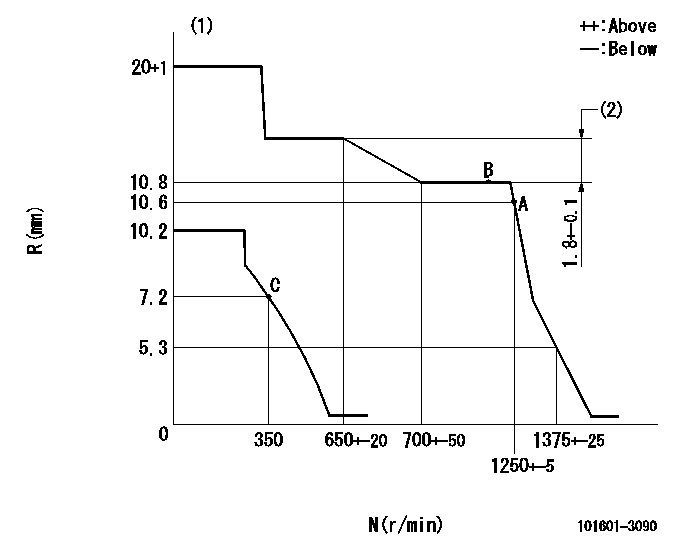
Injection quantity adjustment
Adjusting point
A
Rack position
10.6
Pump speed
r/min
1250
1250
1250
Average injection quantity
mm3/st.
77.5
76.5
78.5
Max. variation between cylinders
%
0
-2
2
Basic
*
Fixing the rack
*
Injection quantity adjustment_02
Adjusting point
B
Rack position
10.8
Pump speed
r/min
1200
1200
1200
Average injection quantity
mm3/st.
78.5
76.5
80.5
Max. variation between cylinders
%
0
-4
4
Fixing the lever
*
Injection quantity adjustment_03
Adjusting point
C
Rack position
8.3+-0.5
Pump speed
r/min
350
350
350
Average injection quantity
mm3/st.
8.9
7.7
10.1
Max. variation between cylinders
%
0
-10
10
Fixing the rack
*
Remarks
Adjust only variation between cylinders; adjust governor according to governor specifications.
Adjust only variation between cylinders; adjust governor according to governor specifications.
Timer adjustment
Pump speed
r/min
700
Advance angle
deg.
0.5
Timer adjustment_02
Pump speed
r/min
750
Advance angle
deg.
0.8
Timer adjustment_03
Pump speed
r/min
900
Advance angle
deg.
1.5
1
2
Timer adjustment_04
Pump speed
r/min
1250
Advance angle
deg.
4
3.5
4.5
Timer adjustment_05
Pump speed
r/min
-
Advance angle
deg.
5
4.5
5.5
Remarks
Measure the actual speed, stop
Measure the actual speed, stop
Test data Ex:
Governor adjustment
N:Pump speed
R:Rack position (mm)
(1)Target notch: K
(2)Rack difference between N = N1 and N = N2
----------
K=12 N1=1200r/min N2=600r/min
----------
----------
K=12 N1=1200r/min N2=600r/min
----------
Speed control lever angle

F:Full speed
I:Idle
(1)Stopper bolt setting
----------
----------
a=23deg+-5deg b=15deg+-5deg
----------
----------
a=23deg+-5deg b=15deg+-5deg
Stop lever angle
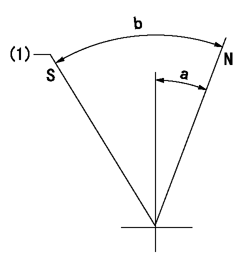
N:Pump normal
S:Stop the pump.
(1)At shipping
----------
----------
a=27deg+-5deg b=53deg+-5deg
----------
----------
a=27deg+-5deg b=53deg+-5deg
Timing setting

(1)Pump vertical direction
(2)Coupling's key groove position at No 1 cylinder's beginning of injection
(3)-
(4)-
----------
----------
a=(0deg)
----------
----------
a=(0deg)
Information:
1. Remove the seat retaining ring (1) and pin (2). 2. Remove the seat (3), bolt (4), washers (5) and spring (6).3. Remove the sleeve and bearing assembly from the cylinder and weight assemblies. 4. Remove the retaining ring (7) from sleeve (8).5. Remove bearing (9) and races (10) from sleeve (8). 6. Remove the valve (11) from piston (12).7. Remove the cylinder-to-weight assembly retaining ring (13).8. Remove the weight assembly (14).9. Remove piston (12) and sleeve (15) from the cylinder (16).10. Remove the O-ring seal from the sleeve (15). 11. Remove the speed limiter plug (17), spring (18), and plunger (19) from the governor housing.12. Remove the high idle screw (21) and low idle screw (20). 13. Remove the lever assembly-to-shaft assembly retaining bolt (23) and lock.14. Remove the shaft assembly (22) and lever assembly (24) from governor housing.15. Remove the seal from governor housing. 16. Remove two retaining bolts (25) and lock. Remove the lever (26) and shaft (27) from idle screw housing.17. Remove two seals and bearing from idle screw housing.Assemble Governor
1. Using tool (A) install the inner seal in idle screw housing with spring side of seal facing the driver. Install bearing and outer seal with lip of the seal toward the inside of the housing. Lubricate lip of seal with clean SAE 30 engine oil.2. Position the shaft and lever in the idle screw housing. Install the retaining bolts and lock. 3. Using tool (A), install the seal in the governor housing with spring side of seal toward inside of governor housing. Lubricate lip of seal with clean SAE 30 engine oil.4. Position the lever assembly and shaft in the governor housing. Install the retaining bolt and lock.5. Install the high and low idle screws in the governor housing.6. Install the speed limiter plug, spring, and plunger in the governor housing. 7. Install the O-ring seal (3) on sleeve (4).8. Install piston (2) and sleeve (4) in the cylinder (1). 9. Position the weight assembly (6) on cylinder (7), and install retaining ring (5). 10. Install the valve (9) in piston (10).11. Install the bearing and races in sleeve. Install retaining ring. Install the sleeve and bearing assembly (8) on valve (9). 12. Position the seat (12), bolt (11), washers and spring on the valve (9). Install the retaining pin (14) and retaining ring (13).concluding step: a) connect governor to fuel injection pump housing
1. Using tool (A) install the inner seal in idle screw housing with spring side of seal facing the driver. Install bearing and outer seal with lip of the seal toward the inside of the housing. Lubricate lip of seal with clean SAE 30 engine oil.2. Position the shaft and lever in the idle screw housing. Install the retaining bolts and lock. 3. Using tool (A), install the seal in the governor housing with spring side of seal toward inside of governor housing. Lubricate lip of seal with clean SAE 30 engine oil.4. Position the lever assembly and shaft in the governor housing. Install the retaining bolt and lock.5. Install the high and low idle screws in the governor housing.6. Install the speed limiter plug, spring, and plunger in the governor housing. 7. Install the O-ring seal (3) on sleeve (4).8. Install piston (2) and sleeve (4) in the cylinder (1). 9. Position the weight assembly (6) on cylinder (7), and install retaining ring (5). 10. Install the valve (9) in piston (10).11. Install the bearing and races in sleeve. Install retaining ring. Install the sleeve and bearing assembly (8) on valve (9). 12. Position the seat (12), bolt (11), washers and spring on the valve (9). Install the retaining pin (14) and retaining ring (13).concluding step: a) connect governor to fuel injection pump housing