Information injection-pump assembly
ZEXEL
101601-3060
1016013060
Rating:
Cross reference number
ZEXEL
101601-3060
1016013060
Zexel num
Bosch num
Firm num
Name
Calibration Data:
Adjustment conditions
Test oil
1404 Test oil ISO4113 or {SAEJ967d}
1404 Test oil ISO4113 or {SAEJ967d}
Test oil temperature
degC
40
40
45
Nozzle and nozzle holder
105780-8140
Bosch type code
EF8511/9A
Nozzle
105780-0000
Bosch type code
DN12SD12T
Nozzle holder
105780-2080
Bosch type code
EF8511/9
Opening pressure
MPa
17.2
Opening pressure
kgf/cm2
175
Injection pipe
Outer diameter - inner diameter - length (mm) mm 6-2-600
Outer diameter - inner diameter - length (mm) mm 6-2-600
Tester oil delivery pressure
kPa
157
157
157
Tester oil delivery pressure
kgf/cm2
1.6
1.6
1.6
Direction of rotation (viewed from drive side)
Right R
Right R
Injection timing adjustment
Direction of rotation (viewed from drive side)
Right R
Right R
Injection order
1-5-3-6-
2-4
Pre-stroke
mm
4
3.95
4.05
Beginning of injection position
Drive side NO.1
Drive side NO.1
Difference between angles 1
Cal 1-5 deg. 60 59.5 60.5
Cal 1-5 deg. 60 59.5 60.5
Difference between angles 2
Cal 1-3 deg. 120 119.5 120.5
Cal 1-3 deg. 120 119.5 120.5
Difference between angles 3
Cal 1-6 deg. 180 179.5 180.5
Cal 1-6 deg. 180 179.5 180.5
Difference between angles 4
Cyl.1-2 deg. 240 239.5 240.5
Cyl.1-2 deg. 240 239.5 240.5
Difference between angles 5
Cal 1-4 deg. 300 299.5 300.5
Cal 1-4 deg. 300 299.5 300.5
Injection quantity adjustment
Adjusting point
A
Rack position
10.4
Pump speed
r/min
1150
1150
1150
Average injection quantity
mm3/st.
78.2
77.2
79.2
Max. variation between cylinders
%
0
-2
2
Basic
*
Fixing the lever
*
Injection quantity adjustment_02
Adjusting point
B
Rack position
7.2+-0.5
Pump speed
r/min
350
350
350
Average injection quantity
mm3/st.
8.9
7.7
10.1
Max. variation between cylinders
%
0
-10
10
Fixing the rack
*
Timer adjustment
Pump speed
r/min
700
Advance angle
deg.
0.5
Timer adjustment_02
Pump speed
r/min
900
Advance angle
deg.
1.4
0.9
1.9
Timer adjustment_03
Pump speed
r/min
1150
Advance angle
deg.
3.5
3
4
Remarks
Finish
Finish
Test data Ex:
Governor adjustment
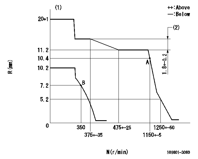
N:Pump speed
R:Rack position (mm)
(1)Target notch: K
(2)Rack difference between N = N1 and N = N2
----------
K=6 N1=500r/min N2=330r/min
----------
----------
K=6 N1=500r/min N2=330r/min
----------
Speed control lever angle
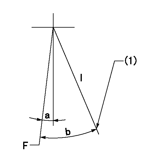
F:Full speed
I:Idle
(1)Stopper bolt setting
----------
----------
a=5deg+-5deg b=20deg+-5deg
----------
----------
a=5deg+-5deg b=20deg+-5deg
Stop lever angle

N:Pump normal
S:Stop the pump.
----------
----------
a=27deg+-5deg b=53deg+-5deg
----------
----------
a=27deg+-5deg b=53deg+-5deg
Information:
Shunt-Type Cooling System
A shunt-type cooling system for the engine is recommended. A shunt-type cooling system radiator has a normal top tank (9) above the radiator core (10) and an expansion tank (2) above (any location) the top tank.An air and coolant tube (7) allows excess air and coolant in the radiator top tank to flow into the expansion tank. The expansion tank has a shunt line (3) which connects to the water pump (11) inlet. The shunt system maintains a positive head of coolant at the pump inlet to prevent cavitation in the pump under all operating conditions.When initially filling the cooling system, the coolant in expansion tank (2) flows through shunt line (3) to the water pump inlet, flows through pump (11), and fills engine cylinder block (13) from the bottom. Coolant flowing into the bottom of the block forces the air out through the top of temperature regulator housing (4), through tube (7) into expansion tank (2).It is a good procedure, after filling the system, to immediately start the engine and make certain the cooling system is full after a few minutes of engine operation. The operating water pump circulates the coolant through the engine, to drive out any air that could have been trapped in the engine. It may be necessary to add more coolant to fill the system.
SHUNT-TYPE RADIATOR COOLING SYSTEM-SCHEMATIC (Temperature regulator partially open)
1-Radiator cap (pressure regulating valve). 2-Expansion tank. 3-Shunt line tube. 4-Temperature regulator (thermostat) housing. 5-Cylinder liners (six). 6-Cylinder head. 7-Air and coolant bleed tube (between radiator top tank and expansion tank). 8-Radiator coolant bypass tube. 9-Radiator top tank. 10-Radiator core. 11-Water pump. 12-Engine lubricating oil cooler. 13-Cylinder block.Cylinder Head
CYLINDER HEAD-END VIEW
1-Precombustion chamber (six). 2-Spring (twelve). 3-Lock (twenty four). 4-Rotocoil assembly (twelve). 5-Rocker arm (twelve). 6-Push rod (twelve). 7-Air inlet manifold (in head). 8-Valve seat insert (six inlet, six exhaust). 9-Valve (six inlet, six exhaust).This overhead valve (OHV) cylinder head has one inlet and one exhaust valve for each engine cylinder. Rocker arms (5) are operated by the camshaft, in the engine cylinder block, cam followers (lifters) and push rods (6) which open and close valves (9) at the proper time. Each rocker arm has an adjustable contact to obtain the recommended valve lash (valve clearance). Each valve spring (2), to close a valve, is retained by locks (3) and a rotocoil assembly (4). The rotocoil will rotate a valve stem approximately one third of a degree each time the valve opens and closes. This will rotate the valve about one revolution per minute when the engine is operating at full load RPM.The valve bushings (guides) and valve seat inserts (8) can be removed, if necessary, and new ones installed. The valve seats are ground at 30° angles. The high heat resistant steel inlet valves and stellite exhaust valves are gound slightly less (about one fourth of a degree) than 30° angles. The interference angles between the valves and valve seats provide for better seating for longer periods of time.The inlet