Information injection-pump assembly
ZEXEL
101601-3030
1016013030
Rating:
Service parts 101601-3030 INJECTION-PUMP ASSEMBLY:
1.
_
2.
FUEL INJECTION PUMP
7.
COUPLING PLATE
8.
_
9.
_
11.
Nozzle and Holder
6138-11-3101
12.
Open Pre:MPa(Kqf/cm2)
24.5{250}
15.
NOZZLE SET
Cross reference number
ZEXEL
101601-3030
1016013030
Zexel num
Bosch num
Firm num
Name
Calibration Data:
Adjustment conditions
Test oil
1404 Test oil ISO4113 or {SAEJ967d}
1404 Test oil ISO4113 or {SAEJ967d}
Test oil temperature
degC
40
40
45
Nozzle and nozzle holder
105780-8140
Bosch type code
EF8511/9A
Nozzle
105780-0000
Bosch type code
DN12SD12T
Nozzle holder
105780-2080
Bosch type code
EF8511/9
Opening pressure
MPa
17.2
Opening pressure
kgf/cm2
175
Injection pipe
Outer diameter - inner diameter - length (mm) mm 6-2-600
Outer diameter - inner diameter - length (mm) mm 6-2-600
Tester oil delivery pressure
kPa
157
157
157
Tester oil delivery pressure
kgf/cm2
1.6
1.6
1.6
Direction of rotation (viewed from drive side)
Right R
Right R
Injection timing adjustment
Direction of rotation (viewed from drive side)
Right R
Right R
Injection order
1-5-3-6-
2-4
Pre-stroke
mm
4
3.95
4.05
Rack position
After adjusting injection quantity. R=A
After adjusting injection quantity. R=A
Beginning of injection position
Drive side NO.1
Drive side NO.1
Difference between angles 1
Cal 1-5 deg. 60 59.5 60.5
Cal 1-5 deg. 60 59.5 60.5
Difference between angles 2
Cal 1-3 deg. 120 119.5 120.5
Cal 1-3 deg. 120 119.5 120.5
Difference between angles 3
Cal 1-6 deg. 180 179.5 180.5
Cal 1-6 deg. 180 179.5 180.5
Difference between angles 4
Cyl.1-2 deg. 240 239.5 240.5
Cyl.1-2 deg. 240 239.5 240.5
Difference between angles 5
Cal 1-4 deg. 300 299.5 300.5
Cal 1-4 deg. 300 299.5 300.5
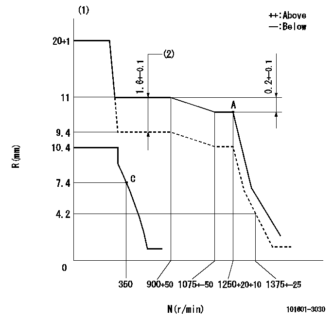
Injection quantity adjustment
Adjusting point
A
Rack position
10.8
Pump speed
r/min
1250
1250
1250
Average injection quantity
mm3/st.
101.5
100.5
102.5
Max. variation between cylinders
%
0
-2
2
Basic
*
Fixing the lever
*
Injection quantity adjustment_02
Adjusting point
C
Rack position
7.4+-0.5
Pump speed
r/min
350
350
350
Average injection quantity
mm3/st.
10.1
8.9
11.3
Max. variation between cylinders
%
0
-10
10
Fixing the rack
*
Boost compensator adjustment
Pump speed
r/min
800
800
800
Rack position
9.4
Boost pressure
kPa
4
2.7
5.3
Boost pressure
mmHg
30
20
40
Boost compensator adjustment_02
Pump speed
r/min
800
800
800
Rack position
11
Boost pressure
kPa
26.7
20
33.4
Boost pressure
mmHg
200
150
250
Timer adjustment
Pump speed
r/min
700
Advance angle
deg.
0.5
Timer adjustment_02
Pump speed
r/min
750
Advance angle
deg.
0.8
Timer adjustment_03
Pump speed
r/min
900
Advance angle
deg.
1.5
1
2
Timer adjustment_04
Pump speed
r/min
1250
Advance angle
deg.
4
3.5
4.5
Timer adjustment_05
Pump speed
r/min
-
Advance angle
deg.
5
4.5
5.5
Remarks
Measure the actual speed, stop
Measure the actual speed, stop
Test data Ex:
Governor adjustment
N:Pump speed
R:Rack position (mm)
(1)Target notch: K
(2)Boost compensator stroke
----------
K=7
----------
----------
K=7
----------
Speed control lever angle
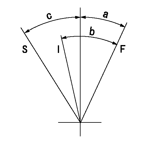
F:Full speed
I:Idle
S:Stop
----------
----------
a=12deg+-5deg b=23deg+-5deg c=32deg+-3deg
----------
----------
a=12deg+-5deg b=23deg+-5deg c=32deg+-3deg
0000001501 LEVER

(F) P/N: Part number of the shim
L1:Thickness (mm)
1. Adjustment of the control lever
(1)Perform idling with the control lever (A) contacting the pushrod (B). At this time, confirm that the spring (C) is not compressed by control lever (A)'s operating torque.
(2)To set the stop position, compress spring (C) using the control lever (A) and adjust the rack so that it contacts the guide screw (D) at position L2. Then, set and fix using the lock nut (E). Adjust the rack position L2 at this time using the shim (F).
(3)Confirm that the control lever (A) returns to the idling position when pulled in the stop direction and then released.
----------
L2=0.2~2mm
----------
----------
L2=0.2~2mm
----------
Information:
FEED ENGAGED
21. Slot. 22. Pin. 23. Knob. To set the feed mechanism into feed on later units, turn lever (A) up (the direction of arrow).
LATER FEED MECHANISM
A. Lever.Place adapter (24) into boring bar and tighten setscrew (25).
ADAPTER INSTALLED
24. 1P2364 Adapter. 25. Setscrew.Apply layout bluing to the bearing cap and bearing bore. Oil the centering rings. Do not use lubricant on the cutter. Use a one-half inch electric drill with universal joint (26) to feed tool through the bore. Service main bearings with .010 in. (0.25 mm) oversize outside diameter are available to permit the bore to be bored oversize. Bore the bore to 3.7175 .0005 in. (94.425 0.013 mm).
BORING BEARING BORE
26. 1P2363 Universal. If you use the later feed mechanism, the tool can be driven from either the boring bar or the feed mechanism.
DRIVING THROUGH FEED MECHANISM (Typical Example)
26. 1P2363 Universal.The bluing applied to the bearing bore indicates the condition of the bore at the correct bore size. If bluing shows an out of round condition, check the largest diameter (indicated by remaining bluing) in relation to the smallest diameter (indicated by lack of bluing). The difference of the two must not exceed .0010 in. (0.025 mm).If bluing indicates a step in the joint face, measure the diameter at the step in relation to the smallest diameter. A step of .0005 in. (0.013 mm) on one or both sides is permissible. A maximum of .0010 in. (0.025 mm) over the nominal finish bore diameter is permissible if within the described limits.To check the bore diameter, set the 1P3535 Dial Bore Gauge to 3.7175 in. (94.425 mm).
CHECKING BORE (Typical Example)Line Boring Main Bearing Bores
Line bore all main bearing bores if bearing caps or saddles are distorted.Clean bearing caps and saddles. Remove all nicks from pan rail. Plug oil holes in block with grease to prevent chips from entering oil passages.Place 1P2344 Centering Rings (1), with oiler (2) up, at each end of block. If an end bore is distorted, use the next good bore. There must be two good bores for locating centering rings.
CENTERING RINGS IN BLOCK
1. 1P2344 Centering Rings. 2. Oiler.Place original bearing caps (4) over the centering rings (1). Tighten bolts (3) hand tight.
CENTERING RINGS INSTALLED
1. 1P2344 Centering Rings. 3. Bolts (four). 4. Bearing caps.
BORING BAR INSTALLED
1. 1P2344 Centering Rings. 3. Bolts (four). 5. 1P2352 Boring Bar.Oil boring bar (5) and insert it through centering rings (1). Tighten bolts (3) to a minimum of 20 lb. ft. (25 N m) and a maximum of 50 lb. ft. (70 N m) while spinning boring bar (5) to check for binding. Centering rings (1) must be seated in bearing saddles after tightening.Slide boring bar (5) out of one end of block and install bearing assemblies (6) on boring bar (5). Slide boring bar (5) back through centering ring. Adjust bearing by tightening bolt (7) until bar begins to bind, then back off until boring bar (5) spins easily.
INSTALLING BEARING ASSEMBLIES
5. 1P2352 Boring Bar. 6. 1P2373 Bearing assembly