Information injection-pump assembly
ZEXEL
101601-3010
1016013010
Rating:
Cross reference number
ZEXEL
101601-3010
1016013010
Zexel num
Bosch num
Firm num
Name
Calibration Data:
Adjustment conditions
Test oil
1404 Test oil ISO4113 or {SAEJ967d}
1404 Test oil ISO4113 or {SAEJ967d}
Test oil temperature
degC
40
40
45
Nozzle and nozzle holder
105780-8140
Bosch type code
EF8511/9A
Nozzle
105780-0000
Bosch type code
DN12SD12T
Nozzle holder
105780-2080
Bosch type code
EF8511/9
Opening pressure
MPa
17.2
Opening pressure
kgf/cm2
175
Injection pipe
Outer diameter - inner diameter - length (mm) mm 6-2-600
Outer diameter - inner diameter - length (mm) mm 6-2-600
Tester oil delivery pressure
kPa
157
157
157
Tester oil delivery pressure
kgf/cm2
1.6
1.6
1.6
Direction of rotation (viewed from drive side)
Right R
Right R
Injection timing adjustment
Direction of rotation (viewed from drive side)
Right R
Right R
Injection order
1-5-3-6-
2-4
Pre-stroke
mm
4
3.95
4.05
Beginning of injection position
Drive side NO.1
Drive side NO.1
Difference between angles 1
Cal 1-5 deg. 60 59.5 60.5
Cal 1-5 deg. 60 59.5 60.5
Difference between angles 2
Cal 1-3 deg. 120 119.5 120.5
Cal 1-3 deg. 120 119.5 120.5
Difference between angles 3
Cal 1-6 deg. 180 179.5 180.5
Cal 1-6 deg. 180 179.5 180.5
Difference between angles 4
Cyl.1-2 deg. 240 239.5 240.5
Cyl.1-2 deg. 240 239.5 240.5
Difference between angles 5
Cal 1-4 deg. 300 299.5 300.5
Cal 1-4 deg. 300 299.5 300.5
Injection quantity adjustment
Adjusting point
A
Rack position
11.3
Pump speed
r/min
1300
1300
1300
Average injection quantity
mm3/st.
87.2
86.2
88.2
Max. variation between cylinders
%
0
-2
2
Basic
*
Fixing the lever
*
Injection quantity adjustment_02
Adjusting point
B
Rack position
7.4+-0.5
Pump speed
r/min
300
300
300
Average injection quantity
mm3/st.
9.8
8.6
11
Max. variation between cylinders
%
0
-10
10
Fixing the rack
*
Timer adjustment
Pump speed
r/min
700
Advance angle
deg.
0.5
Timer adjustment_02
Pump speed
r/min
750
Advance angle
deg.
0.8
Timer adjustment_03
Pump speed
r/min
900
Advance angle
deg.
1.5
1
2
Timer adjustment_04
Pump speed
r/min
1250
Advance angle
deg.
4
3.5
4.5
Timer adjustment_05
Pump speed
r/min
-
Advance angle
deg.
5
4.5
5.5
Remarks
Measure the actual speed, stop
Measure the actual speed, stop
Test data Ex:
Governor adjustment
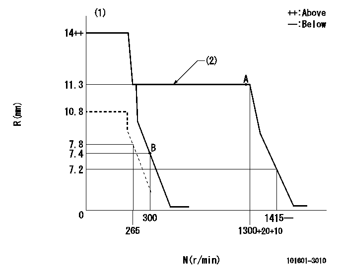
N:Pump speed
R:Rack position (mm)
(1)Target notch: K
(2)Deliver without the torque control spring operating.
----------
K=9
----------
----------
K=9
----------
Speed control lever angle

F:Full speed
I:Idle
(1)Stopper bolt setting
----------
----------
a=29deg+-5deg b=40deg+-5deg
----------
----------
a=29deg+-5deg b=40deg+-5deg
Stop lever angle

N:Pump normal
S:Stop the pump.
----------
----------
a=27deg+-5deg b=53deg+-5deg
----------
----------
a=27deg+-5deg b=53deg+-5deg
Information:
REMOVING CAM FOLLOWERS WITH MAGNET2. Rotate the crankshaft CLOCKWISE (as viewed from front of engine) until the timing mark on crankshaft gear is aligned with timing mark on camshaft large gear.3. Remove the plug from timing pin hole in fuel injection pump housing and install timing pin (1).4. Remove the tachometer drive adapter housing.5. On engines equipped with the hydraulic governor; Remove the automatic timing advance unit or the fuel injection pump camshaft drive gear by removing the tachometer drive shaft with a 9S5031 (5/8 in.) Deep Well Socket. Using puller group (2), thread the 9S8528 Bolt Assembly into the fuel injection pump camshaft. Do not force the bolt assembly. It should thread easily. Install the 9S8527 Bolt by threading it into the automatic timing advance unit or the fuel injection pump camshaft drive gear. Then tighten the 9S8527 Bolt with a wrench until the automatic timing advance unit or fuel injection pump camshaft drive gear "pops" loose.On engines equipped with the "Max-Min" governor; Loosen the automatic timing advance unit retaining bolt with a 8S2357 (9/16in.) Deep Well Socket. The bolt will first feel loose, then it will tighten again when the taper drive of the automatic timing advance unit starts to separate from the camshaft.
TIMING PIN AND PULLER INSTALLED
1. FT887 Timing Pin (Fabricated Tool). 2. 9S8520 Puller Group.6. Remove the camshaft thrust pin (3) from the rear of the cylinder block.
REMOVING THRUST PIN
3. Thrust pin.7. Pull the camshaft (4) out of the cylinder block, being careful to not damage the camshaft bearings or journals.
REMOVING CAMSHAFT
4. Camshaft.Install Camshaft
1. Lubricate the camshaft bearing surfaces with clean engine oil (SAE 30).2. Install the camshaft with timing mark on camshaft gear aligned with timing mark on crankshaft gear.3. Install the camshaft thrust pin in rear of cylinder block. Tighten the thrust pin to 35 5 lb. ft. (4.8 0.7 mkg).4. Position the automatic timing advance unit or fuel injection pump drive gear on the fuel injection pump camshaft. Install the tachometer drive shaft. Engines equipped with the hydraulic governor; Tighten retaining bolt to 32 2 lb. ft. (4.4 0.3 mkg). Engines equipped with the "Max-Min" governor; Tighten retaining bolt to 35 2 lb. ft. (4.8 0.3 mkg).5. Remove timing pin from fuel injection pump housing and install plug in timing pin hole.6. Install the cam followers in the same location from which they were removed. Always use new cam followers with a new camshaft. Be sure to put clean engine oil on the cam followers and camshaft lobes before installing the cam followers.