Information injection-pump assembly
ZEXEL
101601-3000
1016013000
Rating:
Service parts 101601-3000 INJECTION-PUMP ASSEMBLY:
1.
_
2.
FUEL INJECTION PUMP
7.
COUPLING PLATE
8.
_
9.
_
11.
Nozzle and Holder
6138-11-3101
12.
Open Pre:MPa(Kqf/cm2)
24.5{250}
15.
NOZZLE SET
Cross reference number
ZEXEL
101601-3000
1016013000
Zexel num
Bosch num
Firm num
Name
Calibration Data:
Adjustment conditions
Test oil
1404 Test oil ISO4113 or {SAEJ967d}
1404 Test oil ISO4113 or {SAEJ967d}
Test oil temperature
degC
40
40
45
Nozzle and nozzle holder
105780-8140
Bosch type code
EF8511/9A
Nozzle
105780-0000
Bosch type code
DN12SD12T
Nozzle holder
105780-2080
Bosch type code
EF8511/9
Opening pressure
MPa
17.2
Opening pressure
kgf/cm2
175
Injection pipe
Outer diameter - inner diameter - length (mm) mm 6-2-600
Outer diameter - inner diameter - length (mm) mm 6-2-600
Tester oil delivery pressure
kPa
157
157
157
Tester oil delivery pressure
kgf/cm2
1.6
1.6
1.6
Direction of rotation (viewed from drive side)
Right R
Right R
Injection timing adjustment
Direction of rotation (viewed from drive side)
Right R
Right R
Injection order
1-5-3-6-
2-4
Pre-stroke
mm
4
3.95
4.05
Rack position
After adjusting injection quantity. R=A
After adjusting injection quantity. R=A
Beginning of injection position
Drive side NO.1
Drive side NO.1
Difference between angles 1
Cal 1-5 deg. 60 59.5 60.5
Cal 1-5 deg. 60 59.5 60.5
Difference between angles 2
Cal 1-3 deg. 120 119.5 120.5
Cal 1-3 deg. 120 119.5 120.5
Difference between angles 3
Cal 1-6 deg. 180 179.5 180.5
Cal 1-6 deg. 180 179.5 180.5
Difference between angles 4
Cyl.1-2 deg. 240 239.5 240.5
Cyl.1-2 deg. 240 239.5 240.5
Difference between angles 5
Cal 1-4 deg. 300 299.5 300.5
Cal 1-4 deg. 300 299.5 300.5
Injection quantity adjustment
Adjusting point
A
Rack position
10.7
Pump speed
r/min
1250
1250
1250
Average injection quantity
mm3/st.
93.8
92.8
94.8
Max. variation between cylinders
%
0
-2
2
Basic
*
Fixing the lever
*
Boost pressure
kPa
40
40
Boost pressure
mmHg
300
300
Injection quantity adjustment_02
Adjusting point
B
Rack position
11
Pump speed
r/min
900
900
900
Average injection quantity
mm3/st.
97
95
99
Max. variation between cylinders
%
0
-4
4
Fixing the lever
*
Boost pressure
kPa
40
40
Boost pressure
mmHg
300
300
Injection quantity adjustment_03
Adjusting point
C
Rack position
6.8+-0.5
Pump speed
r/min
350
350
350
Average injection quantity
mm3/st.
10.2
9
11.4
Max. variation between cylinders
%
0
-10
10
Fixing the rack
*
Boost pressure
kPa
0
0
0
Boost pressure
mmHg
0
0
0
Boost compensator adjustment
Pump speed
r/min
800
800
800
Rack position
9.4
Boost pressure
kPa
4
2.7
5.3
Boost pressure
mmHg
30
20
40
Boost compensator adjustment_02
Pump speed
r/min
800
800
800
Rack position
11
Boost pressure
kPa
26.7
26.7
26.7
Boost pressure
mmHg
200
200
200
Timer adjustment
Pump speed
r/min
700
Advance angle
deg.
0.5
Timer adjustment_02
Pump speed
r/min
750
Advance angle
deg.
0.8
Timer adjustment_03
Pump speed
r/min
900
Advance angle
deg.
1.5
1
2
Timer adjustment_04
Pump speed
r/min
1250
Advance angle
deg.
4
3.5
4.5
Timer adjustment_05
Pump speed
r/min
-
Advance angle
deg.
5
4.5
5.5
Remarks
Measure the actual speed, stop
Measure the actual speed, stop
Test data Ex:
Governor adjustment
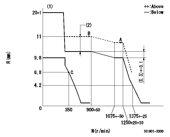
N:Pump speed
R:Rack position (mm)
(1)Target notch: K
(2)Boost compensator stroke: BCL
----------
K=12 BCL=1.6+-0.1mm
----------
----------
K=12 BCL=1.6+-0.1mm
----------
Speed control lever angle
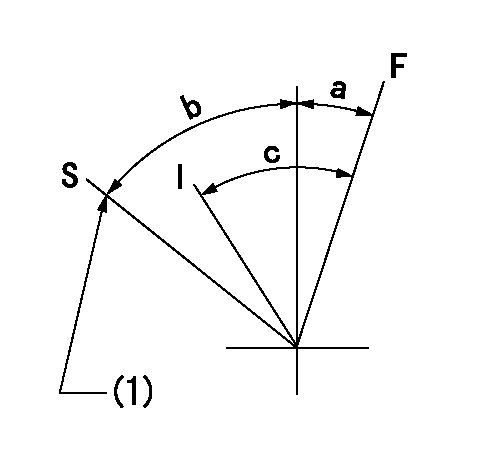
F:Full speed
I:Idle
S:Stop
(1)Stopper bolt setting
----------
----------
a=12deg+-5deg b=32deg+-3deg c=23deg+-5deg
----------
----------
a=12deg+-5deg b=32deg+-3deg c=23deg+-5deg
0000001501 LEVER

(F) P/N: Part number of the shim
L1:Thickness (mm)
1. Adjustment of the control lever
(1)Perform idling with the control lever (A) contacting the pushrod (B). At this time, confirm that the spring (C) is not compressed by control lever (A)'s operating torque.
(2)To set the stop position, compress spring (C) using the control lever (A) and adjust the rack so that it contacts the guide screw (D) at position L2. Then, set and fix using the lock nut (E). Adjust the rack position L2 at this time using the shim (F).
(3)Confirm that the control lever (A) returns to the idling position when pulled in the stop direction and then released.
----------
L2=0.2~2mm
----------
----------
L2=0.2~2mm
----------
Timing setting

(1)Pump vertical direction
(2)Coupling's key groove position at No 1 cylinder's beginning of injection
(3)After adjusting the injection quantity, adjust at rack position aa.
(4)-
----------
aa=10.7mm
----------
a=(0deg)
----------
aa=10.7mm
----------
a=(0deg)
Information:
TIMING MARKS2. Remove the plug from the timing pin hole in fuel injection pump housing and install timing pin (1).
TIMING PIN INSTALLED
1. FT887 Timing Pin (Fabricated Tool).3. Remove the tachometer drive adapter shaft (2).
TACHOMETER DRIVE ADAPTER
2. Tachometer drive adapter shaft.4. Using puller group (3), remove the fuel injection pump camshaft drive gear as follows. Thread the 9S8528 Bolt Assembly into the fuel injection pump camshaft. Do not force the bolt assembly. It should thread easily. Install the 9S8527 Bolt by threading it into the drive gear. Then tighten the 9S8527 Bolt with a wrench until the gear "pops" loose. Remove the gear (4) and the tool setup.
9S8520 PULLER GROUP INSTALLED
3. 9S8520 Puller Group.
REMOVING GEAR
4. Gear.5. Remove retaining screw (5), washer (6), and automatic timing advance (7) from the engine camshaft.
TIMING ADVANCE
5. Retaining screw. 6. Washer. 7. Automatic timing advance.6. Install puller (8), with spacer (10) over the shaft in the camshaft and spacer (9) on spacer (10) as shown and remove the gear from the camshaft.
REMOVING GEAR (Typical Example)
8. 1P2321 Puller. 9. 8S5579 Spacer. 10. 9S9155 Spacer.Install Camshaft Gear
1. Heat the gear to a temperature of approximately 400° F (204° C) before installing on the camshaft.
Do not heat the gear with a torch. Do not heat the gear to a temperature of more than 600° F (315° C). Heating the gear with a torch or to a temperature of more than 600° F (315° C) may cause the two drive dowels for the automatic timing advance to loosen and come out of the gear.
2. Align slot in gear hub with the pin in the camshaft. Install the gear on the camshaft with timing mark on gear aligned with timing mark on crankshaft gear. Be sure the gear is completely seated against the shoulder of the camshaft.
TIMING MARKS
Do not drive the gear on the camshaft. Serious damage can result to camshaft or camshaft thrust pin.
3. Align holes in weights with dowels in gear and install the automatic timing advance.4. Align pin (11) in washer (6) with hole (12) in camshaft and install washer (6).
INSTALLING WASHER
6. Washer. 11. Pin. 12. Hole.5. Install retaining screw (5) and tighten to 108 36 lb. in. (124.5 41.5 cm.kg). Stake screw (5) in two places.
Stake retaining screw (5) carefully. Heavy blows on washer or retaining screw can force the shaft extension too far into the camshaft and eliminate all end clearance.
STAKING SCREW (Typical Example)
5. Retaining screw.6. After retaining screw (5) is staked, the gear and weight assembly requires .003 to .027 in. (0.08 to 0.69 mm) end clearance to prevent binding against the washer, camshaft end, or camshaft gear.7. Position the drive gear on the fuel injection pump camshaft.8. Install the tachometer drive adapter shaft and tighten the shaft retaining nut to 32 2 lb. ft. (4.4 0.3 mkg).9. Remove the timing pin from the fuel injection pump housing and install the plug in the timing hole.