Information injection-pump assembly
ZEXEL
101601-2980
1016012980
HINO
220202670A
220202670a

Rating:
Cross reference number
ZEXEL
101601-2980
1016012980
HINO
220202670A
220202670a
Zexel num
Bosch num
Firm num
Name
Calibration Data:
Adjustment conditions
Test oil
1404 Test oil ISO4113 or {SAEJ967d}
1404 Test oil ISO4113 or {SAEJ967d}
Test oil temperature
degC
40
40
45
Nozzle and nozzle holder
105780-8140
Bosch type code
EF8511/9A
Nozzle
105780-0000
Bosch type code
DN12SD12T
Nozzle holder
105780-2080
Bosch type code
EF8511/9
Opening pressure
MPa
17.2
Opening pressure
kgf/cm2
175
Injection pipe
Outer diameter - inner diameter - length (mm) mm 6-2-600
Outer diameter - inner diameter - length (mm) mm 6-2-600
Overflow valve
131424-5720
Overflow valve opening pressure
kPa
255
221
289
Overflow valve opening pressure
kgf/cm2
2.6
2.25
2.95
Tester oil delivery pressure
kPa
157
157
157
Tester oil delivery pressure
kgf/cm2
1.6
1.6
1.6
Direction of rotation (viewed from drive side)
Right R
Right R
Injection timing adjustment
Direction of rotation (viewed from drive side)
Right R
Right R
Injection order
1-4-2-6-
3-5
Pre-stroke
mm
3.1
3.05
3.15
Beginning of injection position
Drive side NO.1
Drive side NO.1
Difference between angles 1
Cal 1-4 deg. 60 59.5 60.5
Cal 1-4 deg. 60 59.5 60.5
Difference between angles 2
Cyl.1-2 deg. 120 119.5 120.5
Cyl.1-2 deg. 120 119.5 120.5
Difference between angles 3
Cal 1-6 deg. 180 179.5 180.5
Cal 1-6 deg. 180 179.5 180.5
Difference between angles 4
Cal 1-3 deg. 240 239.5 240.5
Cal 1-3 deg. 240 239.5 240.5
Difference between angles 5
Cal 1-5 deg. 300 299.5 300.5
Cal 1-5 deg. 300 299.5 300.5
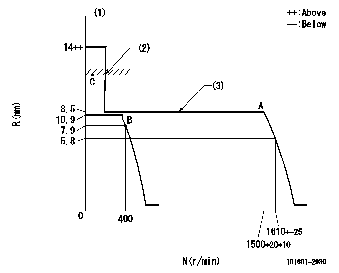
Injection quantity adjustment
Adjusting point
A
Rack position
8.5
Pump speed
r/min
1500
1500
1500
Average injection quantity
mm3/st.
35.4
33.4
37.4
Max. variation between cylinders
%
0
-3
3
Basic
*
Fixing the lever
*
Injection quantity adjustment_02
Adjusting point
-
Rack position
8.4+-0.5
Pump speed
r/min
400
400
400
Average injection quantity
mm3/st.
10
8.5
11.5
Max. variation between cylinders
%
0
-15
15
Fixing the rack
*
Remarks
Adjust only variation between cylinders; adjust governor according to governor specifications.
Adjust only variation between cylinders; adjust governor according to governor specifications.
Injection quantity adjustment_03
Adjusting point
C
Rack position
-
Pump speed
r/min
100
100
100
Average injection quantity
mm3/st.
63
63
73
Fixing the lever
*
Rack limit
*
Timer adjustment
Pump speed
r/min
1200+50
Advance angle
deg.
0
0
0
Timer adjustment_02
Pump speed
r/min
1500
Advance angle
deg.
5
4.7
5.3
Remarks
Finish
Finish
Test data Ex:
Governor adjustment
N:Pump speed
R:Rack position (mm)
(1)Target notch: K
(2)RACK LIMIT
(3)The torque control spring does not operate.
----------
K=13
----------
----------
K=13
----------
Speed control lever angle
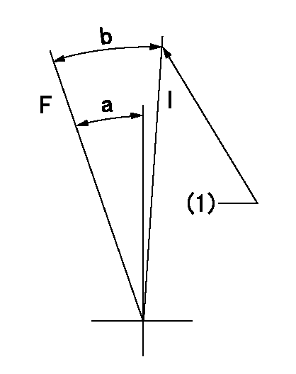
F:Full speed
I:Idle
(1)Stopper bolt setting
----------
----------
a=19deg+-5deg b=27deg+-5deg
----------
----------
a=19deg+-5deg b=27deg+-5deg
Stop lever angle
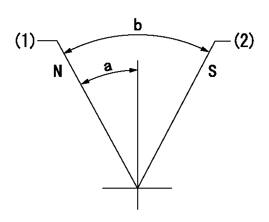
N:Pump normal
S:Stop the pump.
(1)Normal
(2)Rack position aa or less, pump speed bb
----------
aa=7.4mm bb=0r/min
----------
a=27deg+-5deg b=53deg+-5deg
----------
aa=7.4mm bb=0r/min
----------
a=27deg+-5deg b=53deg+-5deg
Timing setting

(1)Pump vertical direction
(2)Position of gear's standard threaded hole at No 1 cylinder's beginning of injection
(3)-
(4)-
----------
----------
a=(70deg)
----------
----------
a=(70deg)
Information:
WATER SLEEVE CLAMP
1. Clamp.3. Use water sleeve tool (2) to move water sleeve (3) into front cover.4. Remove the cylinder head retaining bolts (4) and (5).
MOVING WATER SLEEVE
2. 8S6692 Water Sleeve Tool. 3. Water sleeve.
CYLINDER HEAD
4. Bolts (four each head). 5. Bolts (eighteen each head).
Be sure fuel injection nozzles are removed before removing head. Nozzles extend through the head and nozzle tips can be broken off if nozzles are not removed from the head.
5. Install two 1P7407 Lifting Eye Bolts in the cylinder head. Attach a hoist and remove the cylinder head assembly, the weight is approx. 85 lbs. (39 kg).
REMOVING CYLINDER HEADInstall Cylinder Head Assemblies
1. Clean the mating surfaces of the cylinder head and cylinder block. Install new cylinder head gasket, clean and dry. Clean bores in cylinder head and inspect and lubricate O-rings for water sleeves.2. Install two 1P7407 Lifting Eye Bolts in the cylinder head. Attach a hoist and install the cylinder head assembly. Coat the cylinder head retaining bolt threads with 9M3710 Anti-Seize Compound. Install the bolts and tighten in the following Step sequence. Step A: Tighten bolts 1 through 18 in numerical order to 60 10 lb. ft. (8.3 1.4 mkg).Step B: Retighten bolts 1 through 18 in numerical order to 95 5 lb. ft. (13.1 0.7 mkg).Step C: Finally tighten bolts 1 through 18 in numerical order (hand tighten only) to 95 5 lb. ft. (13.1 0.7 mkg).Step D: Tighten bolts 19, 20, 21, and 22 in numerical order to 32 5 lb. ft. (4.4 0.7 mkg).
CYLINDER HEAD BOLT LOCATION3. Use the 8S6692 Water Sleeve Tool to slide water sleeve into cylinder head and install clamp.Disassemble Cylinder Head
1. Place head on the FT806 Cylinder Head Bench or the 8S6691 Cylinder Head Stand. Use FT967 Adapter Plates to mount head on the FT806 Cylinder Head Bench.2. Use a 5S1330 or 7F4291 Valve Spring Compressor (1) to remove the valves and valve springs.
REMOVING VALVES
1. 5S1330 Valve Spring Compressor illustrated.3. Use the 8S2263 Valve Spring Tester to check valve spring tension.4. The exhaust valve seats have replaceable inserts. To remove, use the 8S7170 Valve Seat Insert Puller Group.
REMOVING EXHAUST VALVE SEAT INSERTS The valve guides are cast in the cylinder head. If the guides show wear or bellmouthing, they can be restored to original tolerances through knurling.Assemble Cylinder Head
1. Lubricate valve stems with clean engine oil (SAE 30) before installing valves into cylinder head. Earlier engines use a valve spring retainer and washer combination instead of the one piece valve spring retainer shown.
CYLINDER HEAD