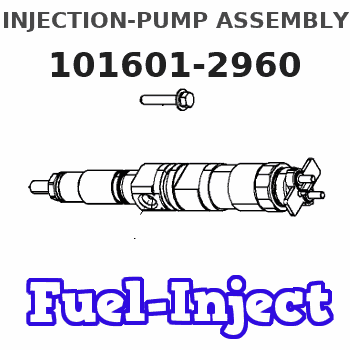
Information injection-pump assembly
ZEXEL
101601-2960
1016012960
HINO
220201550A
220201550a
Rating:
Cross reference number
ZEXEL
101601-2960
1016012960
HINO
220201550A
220201550a
Zexel num
Bosch num
Firm num
Name
Calibration Data:
Adjustment conditions
Test oil
1404 Test oil ISO4113 or {SAEJ967d}
1404 Test oil ISO4113 or {SAEJ967d}
Test oil temperature
degC
40
40
45
Nozzle and nozzle holder
105780-8140
Bosch type code
EF8511/9A
Nozzle
105780-0000
Bosch type code
DN12SD12T
Nozzle holder
105780-2080
Bosch type code
EF8511/9
Opening pressure
MPa
17.2
Opening pressure
kgf/cm2
175
Injection pipe
Outer diameter - inner diameter - length (mm) mm 6-2-600
Outer diameter - inner diameter - length (mm) mm 6-2-600
Overflow valve
134424-0920
Overflow valve opening pressure
kPa
162
147
177
Overflow valve opening pressure
kgf/cm2
1.65
1.5
1.8
Tester oil delivery pressure
kPa
157
157
157
Tester oil delivery pressure
kgf/cm2
1.6
1.6
1.6
Direction of rotation (viewed from drive side)
Right R
Right R
Injection timing adjustment
Direction of rotation (viewed from drive side)
Right R
Right R
Injection order
1-4-2-6-
3-5
Pre-stroke
mm
3.1
3.05
3.15
Beginning of injection position
Drive side NO.1
Drive side NO.1
Difference between angles 1
Cal 1-4 deg. 60 59.5 60.5
Cal 1-4 deg. 60 59.5 60.5
Difference between angles 2
Cyl.1-2 deg. 120 119.5 120.5
Cyl.1-2 deg. 120 119.5 120.5
Difference between angles 3
Cal 1-6 deg. 180 179.5 180.5
Cal 1-6 deg. 180 179.5 180.5
Difference between angles 4
Cal 1-3 deg. 240 239.5 240.5
Cal 1-3 deg. 240 239.5 240.5
Difference between angles 5
Cal 1-5 deg. 300 299.5 300.5
Cal 1-5 deg. 300 299.5 300.5
Injection quantity adjustment
Adjusting point
A
Rack position
10
Pump speed
r/min
1800
1800
1800
Average injection quantity
mm3/st.
60
59
61
Max. variation between cylinders
%
0
-3.5
3.5
Basic
*
Fixing the rack
*
Injection quantity adjustment_02
Adjusting point
C
Rack position
8.7+-0.5
Pump speed
r/min
360
360
360
Average injection quantity
mm3/st.
9
8
10
Max. variation between cylinders
%
0
-10
10
Fixing the rack
*
Injection quantity adjustment_03
Adjusting point
D
Rack position
-
Pump speed
r/min
100
100
100
Average injection quantity
mm3/st.
70
70
80
Fixing the lever
*
Timer adjustment
Pump speed
r/min
1120--
Advance angle
deg.
0
0
0
Remarks
Start
Start
Timer adjustment_02
Pump speed
r/min
1070
Advance angle
deg.
0.5
Timer adjustment_03
Pump speed
r/min
1750
Advance angle
deg.
5
4.5
5.5
Remarks
Finish
Finish
Test data Ex:
Governor adjustment
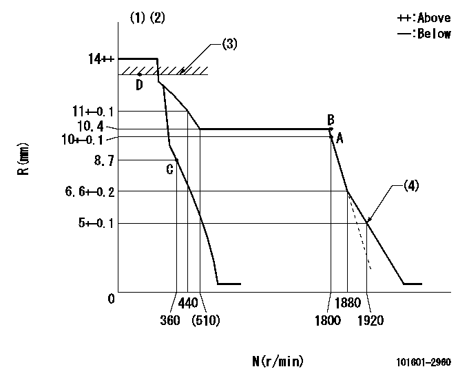
N:Pump speed
R:Rack position (mm)
(1)Target notch: K
(2)Tolerance for racks not indicated: +-0.05mm.
(3)RACK LIMIT
(4)Set idle sub-spring
----------
K=13
----------
----------
K=13
----------
Speed control lever angle

F:Full speed
I:Idle
(1)Stopper bolt setting
----------
----------
a=22deg+-5deg b=34deg+-5deg
----------
----------
a=22deg+-5deg b=34deg+-5deg
Stop lever angle
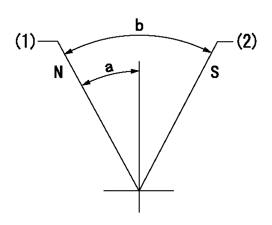
N:Pump normal
S:Stop the pump.
(1)Normal
(2)Rack position aa or less, pump speed bb
----------
aa=8.2mm bb=0r/min
----------
a=27deg+-5deg b=53deg+-5deg
----------
aa=8.2mm bb=0r/min
----------
a=27deg+-5deg b=53deg+-5deg
Timing setting

(1)Pump vertical direction
(2)Coupling's key groove position at No 1 cylinder's beginning of injection
(3)-
(4)-
----------
----------
a=(60deg)
----------
----------
a=(60deg)
Information:
REMOVING COVER
1. Cover.3. Remove screw (2) from rack stop collar (3).
REMOVING SCREW
2. Screw. 3. Rack stop collar.
REMOVING RACK STOP COLLAR
3. Rack stop collar. 4. Spring. 5. Collar.4. Remove rack stop collar (3), spring (4), and collar (5).5. Remove high idle screw (7), bolts (6), and the torque spring. Use wire to fasten the torque spring components together.
HIGH IDLE SCREW
6. Bolts (two). 7. High idle screw.6. Remove the governor housing-to-adapter assembly retaining bolts (8).
GOVERNOR HOUSING RETAINING BOLTS
8. Retaining bolts.
GOVERNOR HOUSING
9. Governor housing. 10. High idle spring.7. Remove governor housing (9) and high idle spring (10).8. Remove the governor spring assembly (11).
REMOVING GOVERNOR SPRING ASSEMBLY
11. Governor spring assembly.9. Remove the bolts (12) and lock (14) from the cylinder and weight assembly (13).
CYLINDER AND WEIGHT ASSEMBLY
12. Bolts. 13. Cylinder and weight assembly. 14. Lock.10. Remove the cylinder and weight assembly (13).
REMOVING CYLINDER AND WEIGHT ASSEMBLY
13. Cylinder and weight assembly.11. Remove piston (15) and spring (16).
REMOVING PISTON
15. Piston. 16. Spring. 17. Bolts.12. Remove the adapter assembly retaining bolts (17) and remove adapter assembly (18) from the fuel injection pump housing.
REMOVING ADAPTER ASSEMBLY
18. Adapter assembly.13. Remove adapter (19) from adapter assembly (18).
REMOVING ADAPTER
18. Adapter assembly. 19. Adapter.Install Governor
1. Put adapter (19) in adapter assembly (18).
INSTALLING ADAPTER
18. Adapter assembly. 19. Adapter.2. Position adapter assembly (18) on fuel injection pump housing so slot in adapter (19) is engaged with groove in rack (20).
INSTALLING ADAPTER ASSEMBLY
18. Adapter assembly. 20. Rack.
INSTALLING PISTON
15. Piston. 16. Spring.3. Install spring (16) and piston (15) in adapter assembly (18).4. Position cylinder and weight assembly (13) on adapter assembly (18) so slot in the piston is engaged with groove in adapter (19).
POSITIONING CYLINDER AND WEIGHT ASSEMBLY
13. Cylinder and weight assembly. 18. Adapter assembly. 19. Adapter.5. Install bolts (12) and lock (14) that hold cylinder and weight assembly (13).
INSTALLING CYLINDER AND WEIGHT ASSEMBLY
12. Bolts. 13. Cylinder and weight assembly. 14. Lock.
INSTALLING GOVERNOR SPRING ASSEMBLY
11. Governor spring assembly.6. Install governor spring assembly (11).7. Install governor high idle spring (10). Position governor housing (9) on the adapter assembly.
INSTALLING GOVERNOR HIGH IDLE SPRING
9. Governor housing. 10. High idle spring.8. Install bolts (8) that hold the governor housing to the adapter assembly.
BOLTS INSTALLED
8. Bolts.
TORQUE SPRING INSTALLED
6. Bolts. 7. High idle screw.9. Install high idle screw (7). Install the torque spring and bolts (6).10. Install spring (4), collar (5), and rack stop collar (3).
INSTALLING RACK STOP COLLAR
3. Rack stop collar. 4. Spring. 5. Collar.11. Install the rack stop collar retaining screw (2).
INSTALLING SCREW
2. Screw. 3. Rack stop collar.
INSTALLING COVER
1. Cover.12. Install the fuel injection pump housing and governor on the engine as a unit. Set the rack and adjust the governor. See the topics FUEL RACK SETTING and GOVERNOR ADJUSTMENTS in TESTING AND ADJUSTING section of the Service Manual.13. Install cover (1) on the rear of the governor.