Information injection-pump assembly
ZEXEL
101601-2930
1016012930
HINO
220004470A
220004470a
Rating:
Service parts 101601-2930 INJECTION-PUMP ASSEMBLY:
1.
_
6.
COUPLING PLATE
7.
COUPLING PLATE
8.
_
9.
_
11.
Nozzle and Holder
23600-1593A
12.
Open Pre:MPa(Kqf/cm2)
21.6{220}
15.
NOZZLE SET
Cross reference number
ZEXEL
101601-2930
1016012930
HINO
220004470A
220004470a
Zexel num
Bosch num
Firm num
Name
Calibration Data:
Adjustment conditions
Test oil
1404 Test oil ISO4113 or {SAEJ967d}
1404 Test oil ISO4113 or {SAEJ967d}
Test oil temperature
degC
40
40
45
Nozzle and nozzle holder
105780-8140
Bosch type code
EF8511/9A
Nozzle
105780-0000
Bosch type code
DN12SD12T
Nozzle holder
105780-2080
Bosch type code
EF8511/9
Opening pressure
MPa
17.2
Opening pressure
kgf/cm2
175
Injection pipe
Outer diameter - inner diameter - length (mm) mm 6-2-600
Outer diameter - inner diameter - length (mm) mm 6-2-600
Overflow valve
131424-5720
Overflow valve opening pressure
kPa
255
221
289
Overflow valve opening pressure
kgf/cm2
2.6
2.25
2.95
Tester oil delivery pressure
kPa
157
157
157
Tester oil delivery pressure
kgf/cm2
1.6
1.6
1.6
Direction of rotation (viewed from drive side)
Right R
Right R
Injection timing adjustment
Direction of rotation (viewed from drive side)
Right R
Right R
Injection order
1-4-2-6-
3-5
Pre-stroke
mm
3.1
3.07
3.13
Beginning of injection position
Drive side NO.1
Drive side NO.1
Difference between angles 1
Cal 1-4 deg. 60 59.75 60.25
Cal 1-4 deg. 60 59.75 60.25
Difference between angles 2
Cyl.1-2 deg. 120 119.75 120.25
Cyl.1-2 deg. 120 119.75 120.25
Difference between angles 3
Cal 1-6 deg. 180 179.75 180.25
Cal 1-6 deg. 180 179.75 180.25
Difference between angles 4
Cal 1-3 deg. 240 239.75 240.25
Cal 1-3 deg. 240 239.75 240.25
Difference between angles 5
Cal 1-5 deg. 300 299.75 300.25
Cal 1-5 deg. 300 299.75 300.25
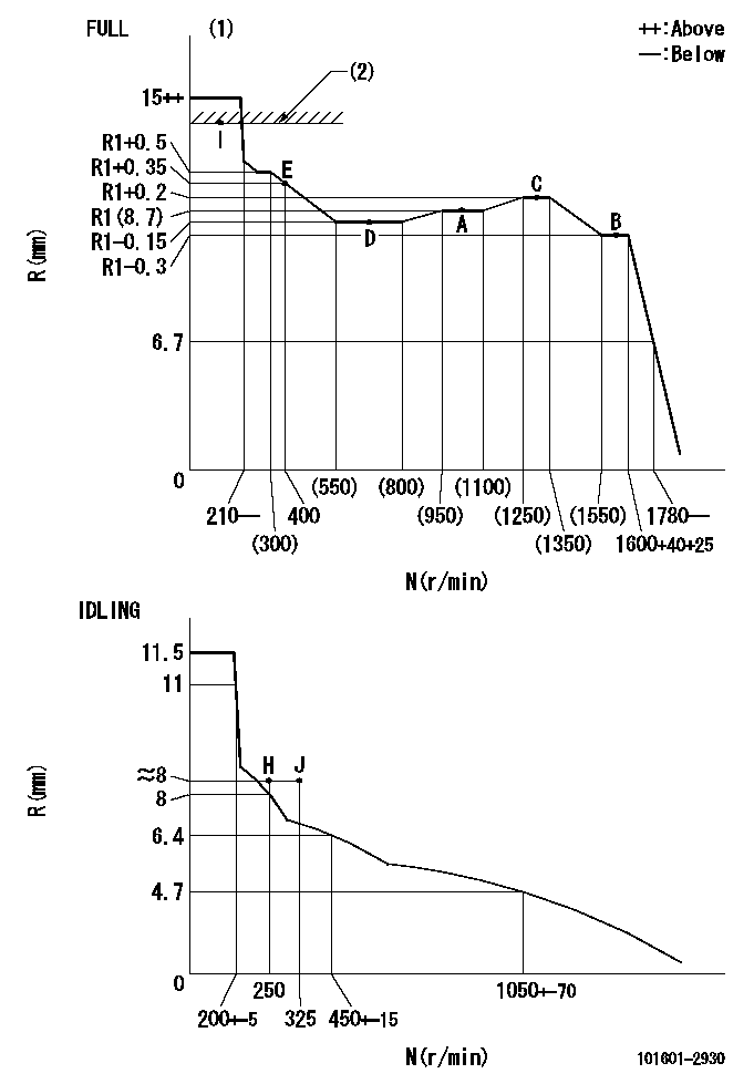
Injection quantity adjustment
Adjusting point
-
Rack position
8.7
Pump speed
r/min
1000
1000
1000
Average injection quantity
mm3/st.
46.6
44.6
48.6
Max. variation between cylinders
%
0
-3.5
3.5
Basic
*
Fixing the rack
*
Standard for adjustment of the maximum variation between cylinders
*
Injection quantity adjustment_02
Adjusting point
H
Rack position
8+-0.5
Pump speed
r/min
250
250
250
Average injection quantity
mm3/st.
8
6.5
9.5
Max. variation between cylinders
%
0
-10
10
Fixing the rack
*
Standard for adjustment of the maximum variation between cylinders
*
Injection quantity adjustment_03
Adjusting point
A
Rack position
R1(8.7)
Pump speed
r/min
1000
1000
1000
Average injection quantity
mm3/st.
46.6
45.6
47.6
Basic
*
Fixing the lever
*
Injection quantity adjustment_04
Adjusting point
B
Rack position
R1-0.3
Pump speed
r/min
1600
1600
1600
Average injection quantity
mm3/st.
45.2
43.2
47.2
Fixing the lever
*
Injection quantity adjustment_05
Adjusting point
C
Rack position
R1+0.2
Pump speed
r/min
1300
1300
1300
Average injection quantity
mm3/st.
52
50
54
Fixing the lever
*
Injection quantity adjustment_06
Adjusting point
D
Rack position
R1-0.15
Pump speed
r/min
650
650
650
Average injection quantity
mm3/st.
38
36
40
Fixing the lever
*
Injection quantity adjustment_07
Adjusting point
I
Rack position
13.5+-0.
5
Pump speed
r/min
100
100
100
Average injection quantity
mm3/st.
95
95
105
Fixing the lever
*
Rack limit
*
Injection quantity adjustment_08
Adjusting point
E
Rack position
R1+0.35
Pump speed
r/min
400
400
400
Average injection quantity
mm3/st.
28
24
32
Fixing the lever
*
Timer adjustment
Pump speed
r/min
1380+50
Advance angle
deg.
0
0
0
Remarks
Start
Start
Timer adjustment_02
Pump speed
r/min
1680
Advance angle
deg.
3.5
3.2
3.8
Remarks
Finish
Finish
Test data Ex:
Governor adjustment
N:Pump speed
R:Rack position (mm)
(1)Torque cam stamping: T1
(2)RACK LIMIT
----------
T1=A76
----------
----------
T1=A76
----------
Speed control lever angle

F:Full speed
I:Idle
(1)Stopper bolt set position 'H'
----------
----------
a=33deg+-3deg b=34deg+-5deg
----------
----------
a=33deg+-3deg b=34deg+-5deg
Stop lever angle

N:Pump normal
S:Stop the pump.
----------
----------
a=40deg+-5deg b=40deg+-5deg
----------
----------
a=40deg+-5deg b=40deg+-5deg
Timing setting

(1)Pump vertical direction
(2)Position of gear's standard threaded hole at No 1 cylinder's beginning of injection
(3)-
(4)-
----------
----------
a=(70deg)
----------
----------
a=(70deg)
Information:
Use extreme care in keeping the work area and tools clean. Handle all parts with care to avoid any damage.
1. Place the nozzle in the holding tool (2) and secure the tool in a vise. Do not clamp any part of the nozzle body directly in the vise.
LOOSENING LOCKNUT
1. Locknut. 2. 8S2250 Nozzle Holding Tool.2. Loosen lift adjusting screw locknut (1). Loosen the lift adjusting screw two or three turns. Loosen pressure screw (3).
LOOSENING PRESSURE SCREW
3. Pressure screw.
PRESSURE SCREW ASSEMBLY REMOVED3. Holding the nozzle in one hand, invert it and back out the pressure screw allowing the spring, spring seat and shims to fall into your hand. The valve may slide out, by its own weight, and should be handled carefully by its stem.4. If the valve does not fall out, remove it with retractor (4). To prevent bending the valve, bottom it in the body with the retractor. Push down on the retractor body to mount the collet. Turn the knurled nut counterclockwise to secure the collet and withdraw the valve.
REMOVING VALVE
4. 5P958 Valve Retractor.5. Place the parts in solvent to loosen carbon and deposits of foreign material. Do not soak the body assembly in solvent for over 1 to 2 hours. The solvent can damage the epoxy bond used to secure the body assembly components together.Assemble Fuel Injection Nozzle (9L7883 Nozzles)
Before assembly, wash all parts thoroughly. Flush the body to remove any debris or lapping compound. Assemble while all parts are wet with clean fuel.1. Handle valve (1) by its shank and slide it partially into the body.
ASSEMBLENG NOZZLE
1. Valve. 2. Spring seat. 3. Spring. 4. Shims. 5. Pressure screw. 6. Locknut. 7. Lift adjusting screw.2. Assemble lift adjusting screw (7) into pressure screw (5) two to three turns and install locknut (6), do not tighten the locknut. Put shims (4), spring (3), and spring seat (2) on the lift adjusting screw. Put the thickest shim (4) against the screw.3. Tilt the nozzle body and with spring seat (2) in contact with the top of valve (1), push the valve and spring components into the body and tighten the pressure screw hand tight.4. Put the nozzle in the 8S2250 Nozzle Holding Tool. Put the holding tool in a vise and tighten the pressure screw (5) to 75 to 80 lb. in. (86.5 to 92.2 cm.kg).
TIGHTENING PRESSURE SCREW To check or adjust the opening pressure and the valve lift see the TESTING AND ADJUSTING section of the Service Manual.5. To tighten the locknut, hold lift adjusting screw (7) with a screwdriver and tighten the locknut (6) just enough so lift adjusting screw (7) will not turn.
TIGHTENING LOCKNUT6. Use a torque wrench and tighten the locknut to 35 to 40 lb. in. (40.4 to 46.1 cm.kg).
TIGHTENING LOCKNUTService And Inspect Fuel Injection Nozzle (9L7883 Nozzles)
1. Use the brush (4) to clean the tip and body exterior.2. Secure the 8S2247 Cleaning Wire [.008 to .009 in. (0.20 to 0.23 mm) dia.] in pin vise (1) with 1/32 in. (0.79 mm)