Information injection-pump assembly
ZEXEL
101601-2891
1016012891
HINO
220801212B
220801212b

Rating:
Cross reference number
ZEXEL
101601-2891
1016012891
HINO
220801212B
220801212b
Zexel num
Bosch num
Firm num
Name
101601-2891
220801212B HINO
INJECTION-PUMP ASSEMBLY
H07C * K
H07C * K
Calibration Data:
Adjustment conditions
Test oil
1404 Test oil ISO4113 or {SAEJ967d}
1404 Test oil ISO4113 or {SAEJ967d}
Test oil temperature
degC
40
40
45
Nozzle and nozzle holder
105780-8140
Bosch type code
EF8511/9A
Nozzle
105780-0000
Bosch type code
DN12SD12T
Nozzle holder
105780-2080
Bosch type code
EF8511/9
Opening pressure
MPa
17.2
Opening pressure
kgf/cm2
175
Injection pipe
Outer diameter - inner diameter - length (mm) mm 6-2-600
Outer diameter - inner diameter - length (mm) mm 6-2-600
Overflow valve
134424-0920
Overflow valve opening pressure
kPa
162
147
177
Overflow valve opening pressure
kgf/cm2
1.65
1.5
1.8
Tester oil delivery pressure
kPa
157
157
157
Tester oil delivery pressure
kgf/cm2
1.6
1.6
1.6
Direction of rotation (viewed from drive side)
Right R
Right R
Injection timing adjustment
Direction of rotation (viewed from drive side)
Right R
Right R
Injection order
1-4-2-6-
3-5
Pre-stroke
mm
3.1
3.07
3.13
Beginning of injection position
Drive side NO.1
Drive side NO.1
Difference between angles 1
Cal 1-4 deg. 60 59.75 60.25
Cal 1-4 deg. 60 59.75 60.25
Difference between angles 2
Cyl.1-2 deg. 120 119.75 120.25
Cyl.1-2 deg. 120 119.75 120.25
Difference between angles 3
Cal 1-6 deg. 180 179.75 180.25
Cal 1-6 deg. 180 179.75 180.25
Difference between angles 4
Cal 1-3 deg. 240 239.75 240.25
Cal 1-3 deg. 240 239.75 240.25
Difference between angles 5
Cal 1-5 deg. 300 299.75 300.25
Cal 1-5 deg. 300 299.75 300.25
Injection quantity adjustment
Adjusting point
A
Rack position
6.9
Pump speed
r/min
900
900
900
Average injection quantity
mm3/st.
65
64
66
Max. variation between cylinders
%
0
-3.5
3.5
Basic
*
Fixing the lever
*
Injection quantity adjustment_02
Adjusting point
B
Rack position
5+-0.5
Pump speed
r/min
375
375
375
Average injection quantity
mm3/st.
8
7
9
Max. variation between cylinders
%
0
-10
10
Fixing the rack
*
Remarks
Adjust only variation between cylinders; adjust governor according to governor specifications.
Adjust only variation between cylinders; adjust governor according to governor specifications.
Injection quantity adjustment_03
Adjusting point
C
Rack position
10.8+-0.
5
Pump speed
r/min
100
100
100
Average injection quantity
mm3/st.
125
125
135
Fixing the lever
*
Rack limit
*
Injection quantity adjustment_04
Adjusting point
E
Rack position
7.2
Pump speed
r/min
600
600
600
Average injection quantity
mm3/st.
56
55
57
Fixing the lever
*
Timer adjustment
Pump speed
r/min
1250
Advance angle
deg.
0.5
Timer adjustment_02
Pump speed
r/min
1300
Advance angle
deg.
1.5
1
2
Timer adjustment_03
Pump speed
r/min
1430
Advance angle
deg.
4.5
4
5
Remarks
Finish
Finish
Test data Ex:
Governor adjustment
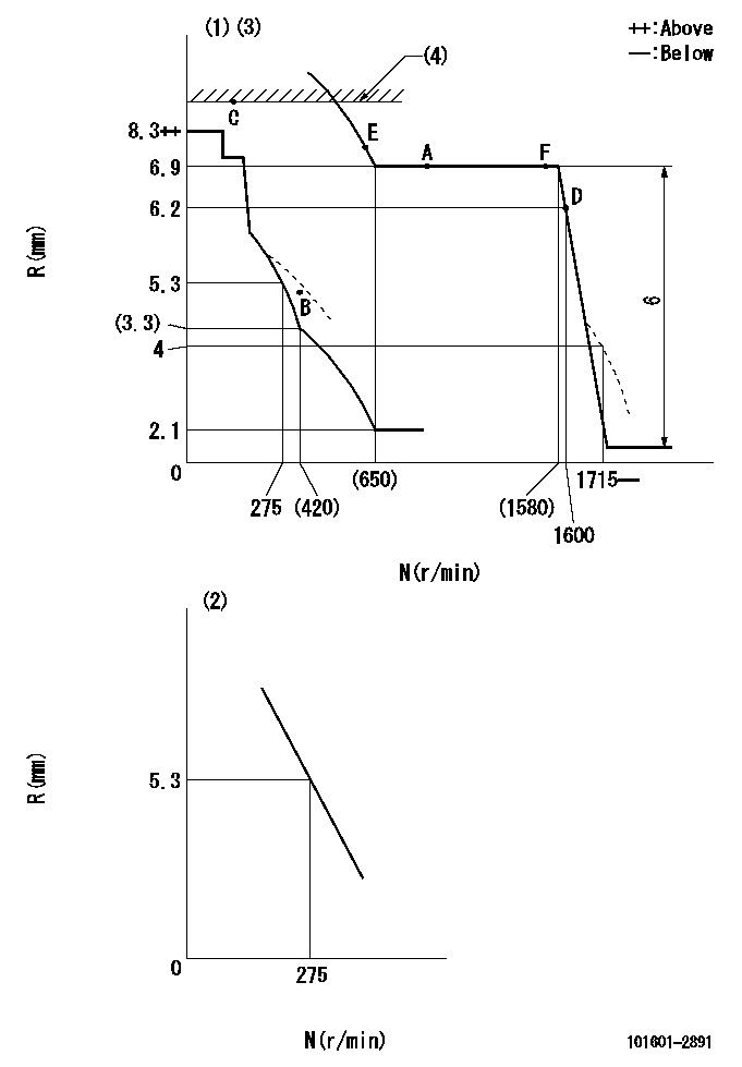
N:Pump speed
R:Rack position (mm)
(1)Adjust with speed control lever at full position (minimum-maximum speed specification)
(2)Adjust with the load control lever in the full position (variable speed specification).
(3)Beginning of damper spring operation: DL
(4)RACK LIMIT
----------
DL=6-0.2mm
----------
----------
DL=6-0.2mm
----------
Speed control lever angle

F:Full speed
I:Idle
----------
----------
a=14deg+-5deg b=(20deg)+-5deg
----------
----------
a=14deg+-5deg b=(20deg)+-5deg
0000000901

F:Full load
I:Idle
(1)Use the hole at R = aa
(2)Stopper bolt setting
----------
aa=65mm
----------
a=25.5deg+-3deg b=2deg+-5deg
----------
aa=65mm
----------
a=25.5deg+-3deg b=2deg+-5deg
Stop lever angle
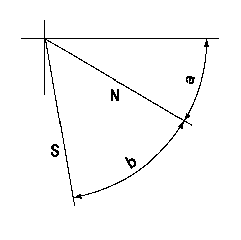
N:Pump normal
S:Stop the pump.
----------
----------
a=35deg+-5deg b=50deg+-5deg
----------
----------
a=35deg+-5deg b=50deg+-5deg
0000001201
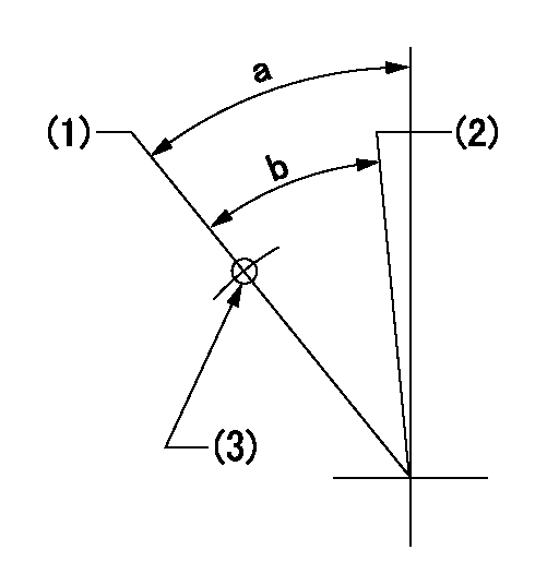
(1)Minimum - maximum speed specification
(2)Variable speed specification
(3)Use the hole at R = aa
----------
aa=65mm
----------
a=39.5deg+-6deg b=(31.5deg)
----------
aa=65mm
----------
a=39.5deg+-6deg b=(31.5deg)
Timing setting

(1)Pump vertical direction
(2)Coupling's key groove position at No 1 cylinder's beginning of injection
(3)-
(4)-
----------
----------
a=(60deg)
----------
----------
a=(60deg)
Information:
Engine Crankshaft Turns Free Exhaust Smoke Can Be Seen While Starting Recommended Procedure1. Cold Outside Temperatures It can be necessary to use starting aids, or warm engine oil or coolant, at temperatures below 10° F (-12° C).2. Air in Fuel System With air in the fuel system the engine will normally be difficult to start, run rough and release a large amount of white smoke. Remove the air from the fuel system by either loosening the cap on the tee at the fuel filter, or by loosening the fuel line nuts one at a time at the cylinder heads. Turn the engine with the starter until the fuel flow at this connection is free of air. If air is not removed in this way put 5 psi (0,35 kg/cm2) [CAUTION do not use more than 8 psi (0,56 kg/cm2)] of air pressure to the tank and check for leaks at connections between the fuel tank and the fuel transfer pump. If there are no leaks at the connections, remove the fuel supply line from the tank and connect to an outside fuel supply. If this corrects the problem the suction line (standpipe) inside the fuel tank has a leak.3. Low Quality Fuel Remove a small amount of fuel from the tank and check for water in the fuel. If there is water in the fuel, remove fuel from the tank until it is free of water and fill with a good quality fuel. Change the fuel filter and "prime" (remove the air and/or low quality fuel from the fuel system) the fuel system as per the Operation Guide (FEO45119). If there is no water in the fuel, using an outside supply of fuel, prime and start the engine. If engine starts correctly using different fuel, remove all fuel from the tank and fill with good quality fuel and prime the fuel system.4. Fuel Injection Timing Not Correct Check and make necessary adjustments as per Testing and Adjusting section of the Service Manual.5. Valve Adjustment Not Correct Check and make necessary adjustments as per Testing and Adjusting section of the Service Manual. Intake valve adjustment is .015 in. (0,38 mm) and exhaust valve adjustment is .025 in. (0,64 mm).6. Bad Fuel Nozzle(s) Remove the fuel nozzles and test as per Testing and Adjusting section of the Service Manual.7. Low Compression See the chart Misfiring and Running Rough. Exhaust Smoke Can Not Be Seen While Starting8. No Fuel in Tank Check fuel level visually (do not use the fuel gauge only). Be sure tank selection valve is open to the tank with fuel in it. Be sure valve in fuel line between the tanks is open.9. No Fuel From Fuel Injection Pump Loosen one or more of the fuel injection line nuts at the cylinder heads. With ignition switch on and accelerator in the fuel on position, turn the engine with the starter to be sure there is no fuel from the fuel injection pump. To find the cause
Have questions with 101601-2891?
Group cross 101601-2891 ZEXEL
Hino
101601-2891
220801212B
INJECTION-PUMP ASSEMBLY
H07C
H07C