Information injection-pump assembly
BOSCH
9 400 614 575
9400614575
ZEXEL
101601-2870
1016012870
HINO
220004171C
220004171c

Rating:
Service parts 101601-2870 INJECTION-PUMP ASSEMBLY:
1.
_
7.
COUPLING PLATE
8.
_
9.
_
11.
Nozzle and Holder
236001632A
12.
Open Pre:MPa(Kqf/cm2)
21.6(220)

15.
NOZZLE SET
Cross reference number
BOSCH
9 400 614 575
9400614575
ZEXEL
101601-2870
1016012870
HINO
220004171C
220004171c
Zexel num
Bosch num
Firm num
Name
101601-2870
9 400 614 575
220004171C HINO
INJECTION-PUMP ASSEMBLY
H07C * K
H07C * K
Calibration Data:
Adjustment conditions
Test oil
1404 Test oil ISO4113 or {SAEJ967d}
1404 Test oil ISO4113 or {SAEJ967d}
Test oil temperature
degC
40
40
45
Nozzle and nozzle holder
105780-8140
Bosch type code
EF8511/9A
Nozzle
105780-0000
Bosch type code
DN12SD12T
Nozzle holder
105780-2080
Bosch type code
EF8511/9
Opening pressure
MPa
17.2
Opening pressure
kgf/cm2
175
Injection pipe
Outer diameter - inner diameter - length (mm) mm 6-2-600
Outer diameter - inner diameter - length (mm) mm 6-2-600
Overflow valve
134424-0920
Overflow valve opening pressure
kPa
162
147
177
Overflow valve opening pressure
kgf/cm2
1.65
1.5
1.8
Tester oil delivery pressure
kPa
157
157
157
Tester oil delivery pressure
kgf/cm2
1.6
1.6
1.6
Direction of rotation (viewed from drive side)
Right R
Right R
Injection timing adjustment
Direction of rotation (viewed from drive side)
Right R
Right R
Injection order
1-4-2-6-
3-5
Pre-stroke
mm
3.1
3.07
3.13
Beginning of injection position
Drive side NO.1
Drive side NO.1
Difference between angles 1
Cal 1-4 deg. 60 59.75 60.25
Cal 1-4 deg. 60 59.75 60.25
Difference between angles 2
Cyl.1-2 deg. 120 119.75 120.25
Cyl.1-2 deg. 120 119.75 120.25
Difference between angles 3
Cal 1-6 deg. 180 179.75 180.25
Cal 1-6 deg. 180 179.75 180.25
Difference between angles 4
Cal 1-3 deg. 240 239.75 240.25
Cal 1-3 deg. 240 239.75 240.25
Difference between angles 5
Cal 1-5 deg. 300 299.75 300.25
Cal 1-5 deg. 300 299.75 300.25
Injection quantity adjustment
Adjusting point
-
Rack position
8.8
Pump speed
r/min
900
900
900
Average injection quantity
mm3/st.
65
64
66
Max. variation between cylinders
%
0
-3.5
3.5
Basic
*
Fixing the rack
*
Standard for adjustment of the maximum variation between cylinders
*
Injection quantity adjustment_02
Adjusting point
H
Rack position
6.9+-0.5
Pump speed
r/min
375
375
375
Average injection quantity
mm3/st.
8
7
9
Max. variation between cylinders
%
0
-10
10
Fixing the rack
*
Standard for adjustment of the maximum variation between cylinders
*
Injection quantity adjustment_03
Adjusting point
A
Rack position
R1(8.8)
Pump speed
r/min
900
900
900
Average injection quantity
mm3/st.
65
64
66
Basic
*
Fixing the lever
*
Injection quantity adjustment_04
Adjusting point
B
Rack position
8.2+-0.5
Pump speed
r/min
1600
1600
1600
Average injection quantity
mm3/st.
50
45
55
Fixing the lever
*
Injection quantity adjustment_05
Adjusting point
C
Rack position
R1+0.3
Pump speed
r/min
600
600
600
Average injection quantity
mm3/st.
56
55
57
Fixing the lever
*
Injection quantity adjustment_06
Adjusting point
I
Rack position
-
Pump speed
r/min
100
100
100
Average injection quantity
mm3/st.
115
115
Fixing the lever
*
Timer adjustment
Pump speed
r/min
1250
Advance angle
deg.
0.5
Timer adjustment_02
Pump speed
r/min
1300
Advance angle
deg.
1.5
1
2
Timer adjustment_03
Pump speed
r/min
1430
Advance angle
deg.
4.5
4.2
4.8
Remarks
Finish
Finish
Test data Ex:
Governor adjustment
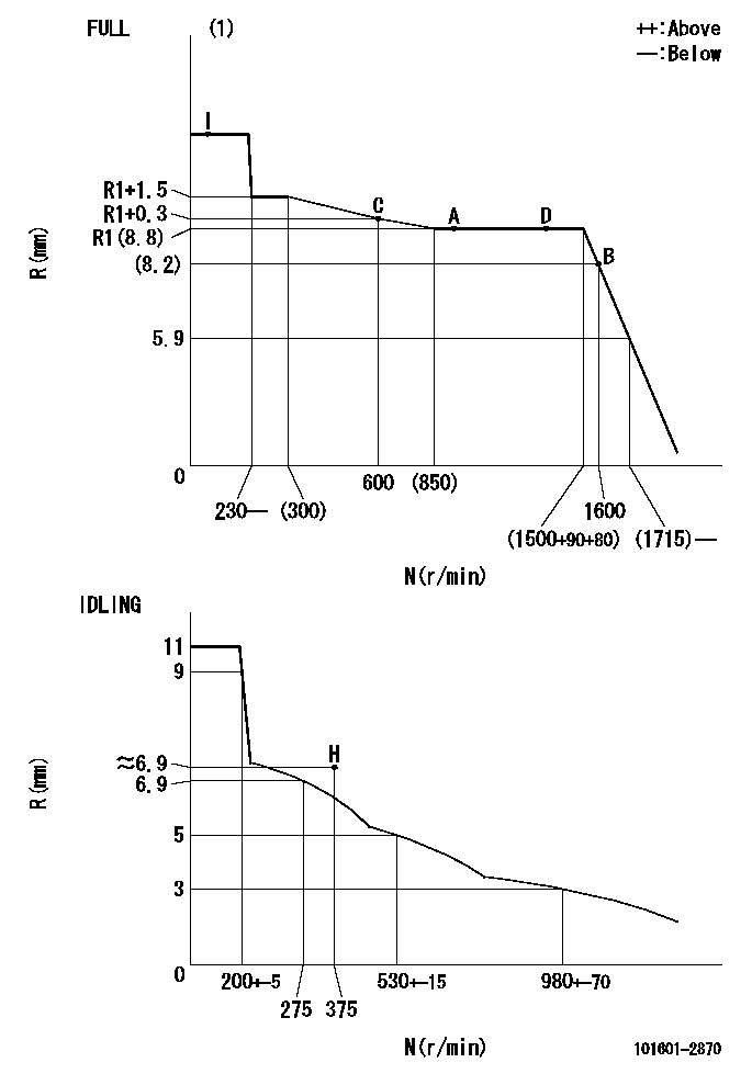
N:Pump speed
R:Rack position (mm)
(1)Torque cam stamping: T1
----------
T1=A12
----------
----------
T1=A12
----------
Speed control lever angle

F:Full speed
I:Idle
(1)Stopper bolt set position 'H'
----------
----------
a=32deg+-5deg b=(43deg)+-3deg
----------
----------
a=32deg+-5deg b=(43deg)+-3deg
Stop lever angle
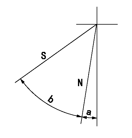
N:Pump normal
S:Stop the pump.
----------
----------
a=5deg+-5deg b=40deg+-5deg
----------
----------
a=5deg+-5deg b=40deg+-5deg
Timing setting

(1)Pump vertical direction
(2)Coupling's key groove position at No 1 cylinder's beginning of injection
(3)-
(4)-
----------
----------
a=(60deg)
----------
----------
a=(60deg)
Information:
Recommended Procedure1. Air in Fuel System With air in the fuel system the engine will normally be difficult to start, run rough and release a large amount of white smoke. Remove the air from the fuel system by either loosening the cap on the tee at the fuel filter or by loosening the fuel line nuts one at a time at the cylinder heads. Turn the engine with the starter until the fuel flow at this connection is free of air. If air is not removed in this way, put 5 psi (0,35 kg/cm2) [CAUTION do not use more than 8 psi (0,56 kg/cm2)] of air pressure to the fuel tank and check for leaks at connections between the fuel tank and the fuel transfer pump. If there are no leaks at the connections, remove the fuel supply line from the tank and connect it to an outside fuel supply. If this corrects the problem the suction line (standpipe) inside the fuel tank has a leak.2. Valve Adjustment Not Correct Check and make necessary adjustments as per Testing and Adjusting section of the Service Manual. Intake valve adjustment is .015 in. (0,38 mm) and exhaust valve adjustment is .025 in. (0,64 mm).3. Fuel Injection Timing Not Correct Check and make necessary adjustments as per Testing and Adjusting section of the Service Manual.4. Automatic Timing Advance Does Not Operate Correctly Check with engine warm. Use the 1P3500 Timing Light Group. Special Instruction (SMHS6964) gives the test procedure. If the timing light is not available, make rapid "acceleration" (increase in speed) from low idle to high idle. Engine must have smooth acceleration. A timing advance that does not operate correctly can cause delays of the engine acceleration at some rpm before high idle, or possibly cause the engine to run rough and have exhaust noise (backfire) during acceleration. This condition is difficult to find if engine acceleration is slow or at a constant engine rpm.5. Bad Fuel Nozzle(s) Find a bad nozzle by running engine at the rpm range where it runs rough. Loosen the fuel line nut at the cylinder head enough to stop fuel supply to that cylinder. Each cylinder must be checked this way. If a cylinder is found where loosening of the nut makes no difference in the rough running, test the nozzle for that cylinder. To test a nozzle, remove the nozzle from the engine and test as per Testing and Adjusting section of the Service Manual.6. Valve Leakage; Wear or Damage to Pistons and/or Piston Rings; Wear or Damage to Cylinder Walls Check with the cylinder leakage tester. If leakage is over specification and leaking is heard at the air inlet to the engine (intake valve leaks), exhaust manifold (exhaust valve leaks), or at the oil filler opening (leaking past piston rings). Special Instruction (GMG00694) gives the test procedure.7. Cylinder Head Gasket Leakage Check with the cylinder leakage tester. If leakage is higher than specification, check at the fuel nozzle hole of the
Have questions with 101601-2870?
Group cross 101601-2870 ZEXEL
Hino
101601-2870
9 400 614 575
220004171C
INJECTION-PUMP ASSEMBLY
H07C
H07C