Information injection-pump assembly
ZEXEL
101601-2810
1016012810
HINO
220004240A
220004240a
Rating:
Cross reference number
ZEXEL
101601-2810
1016012810
HINO
220004240A
220004240a
Zexel num
Bosch num
Firm num
Name
Calibration Data:
Adjustment conditions
Test oil
1404 Test oil ISO4113 or {SAEJ967d}
1404 Test oil ISO4113 or {SAEJ967d}
Test oil temperature
degC
40
40
45
Nozzle and nozzle holder
105780-8140
Bosch type code
EF8511/9A
Nozzle
105780-0000
Bosch type code
DN12SD12T
Nozzle holder
105780-2080
Bosch type code
EF8511/9
Opening pressure
MPa
17.2
Opening pressure
kgf/cm2
175
Injection pipe
Outer diameter - inner diameter - length (mm) mm 6-2-600
Outer diameter - inner diameter - length (mm) mm 6-2-600
Overflow valve
131424-5720
Overflow valve opening pressure
kPa
255
221
289
Overflow valve opening pressure
kgf/cm2
2.6
2.25
2.95
Tester oil delivery pressure
kPa
157
157
157
Tester oil delivery pressure
kgf/cm2
1.6
1.6
1.6
Direction of rotation (viewed from drive side)
Right R
Right R
Injection timing adjustment
Direction of rotation (viewed from drive side)
Right R
Right R
Injection order
1-4-2-6-
3-5
Pre-stroke
mm
3.1
3.07
3.13
Beginning of injection position
Drive side NO.1
Drive side NO.1
Difference between angles 1
Cal 1-4 deg. 60 59.75 60.25
Cal 1-4 deg. 60 59.75 60.25
Difference between angles 2
Cyl.1-2 deg. 120 119.75 120.25
Cyl.1-2 deg. 120 119.75 120.25
Difference between angles 3
Cal 1-6 deg. 180 179.75 180.25
Cal 1-6 deg. 180 179.75 180.25
Difference between angles 4
Cal 1-3 deg. 240 239.75 240.25
Cal 1-3 deg. 240 239.75 240.25
Difference between angles 5
Cal 1-5 deg. 300 299.75 300.25
Cal 1-5 deg. 300 299.75 300.25
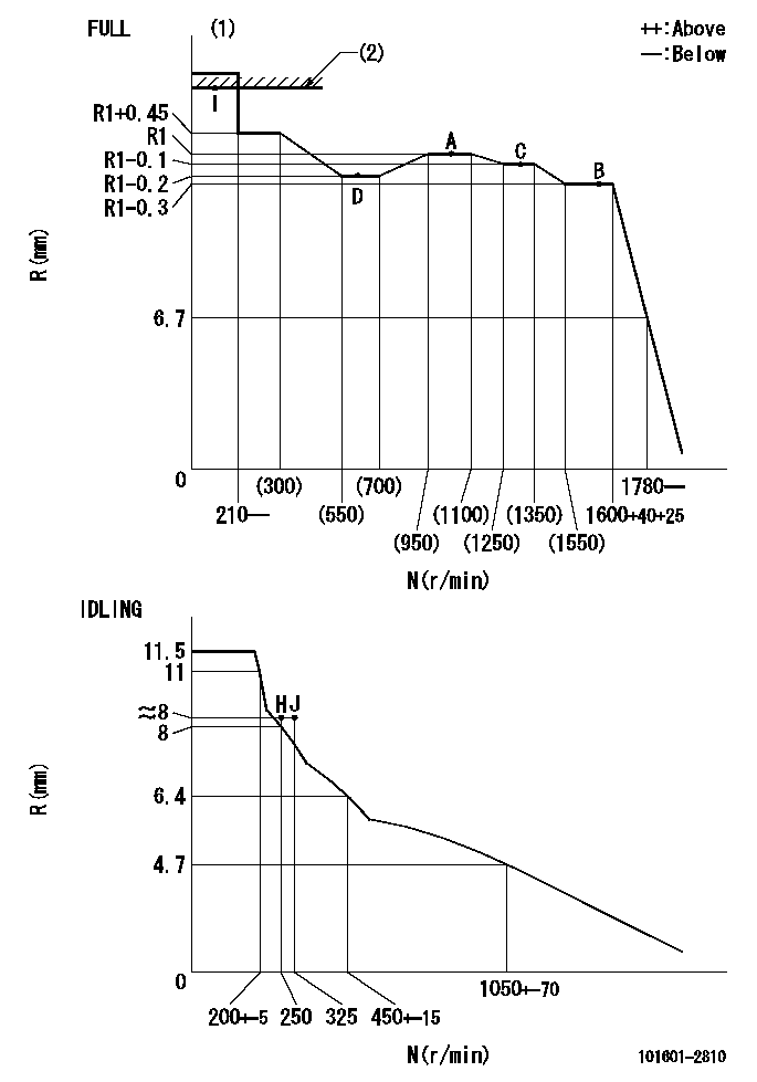
Injection quantity adjustment
Adjusting point
-
Rack position
8.7
Pump speed
r/min
1000
1000
1000
Average injection quantity
mm3/st.
44.4
42.4
46.4
Max. variation between cylinders
%
0
-3.5
3.5
Basic
*
Fixing the rack
*
Standard for adjustment of the maximum variation between cylinders
*
Injection quantity adjustment_02
Adjusting point
H
Rack position
8+-0.5
Pump speed
r/min
250
250
250
Average injection quantity
mm3/st.
8
6.5
9.5
Max. variation between cylinders
%
0
-10
10
Fixing the rack
*
Standard for adjustment of the maximum variation between cylinders
*
Injection quantity adjustment_03
Adjusting point
A
Rack position
R1(8.7)
Pump speed
r/min
1000
1000
1000
Average injection quantity
mm3/st.
44.4
43.4
45.4
Basic
*
Fixing the lever
*
Injection quantity adjustment_04
Adjusting point
B
Rack position
R1-0.3
Pump speed
r/min
1600
1600
1600
Average injection quantity
mm3/st.
43.5
41.5
45.5
Fixing the lever
*
Injection quantity adjustment_05
Adjusting point
C
Rack position
R1-0.1
Pump speed
r/min
1300
1300
1300
Average injection quantity
mm3/st.
44.1
42.1
46.1
Fixing the lever
*
Injection quantity adjustment_06
Adjusting point
D
Rack position
R1-0.2
Pump speed
r/min
650
650
650
Average injection quantity
mm3/st.
36.2
34.2
38.2
Fixing the lever
*
Injection quantity adjustment_07
Adjusting point
I
Rack position
13.5+-0.
5
Pump speed
r/min
100
100
100
Average injection quantity
mm3/st.
95
95
105
Fixing the lever
*
Rack limit
*
Timer adjustment
Pump speed
r/min
1300+50
Advance angle
deg.
0
0
0
Remarks
Start
Start
Timer adjustment_02
Pump speed
r/min
1600
Advance angle
deg.
5
4.7
5.3
Remarks
Finish
Finish
Test data Ex:
Governor adjustment
N:Pump speed
R:Rack position (mm)
(1)Torque cam stamping: T1
(2)RACK LIMIT
----------
T1=93
----------
----------
T1=93
----------
Speed control lever angle

F:Full speed
I:Idle
(1)Stopper bolt set position 'H'
----------
----------
a=32.5deg+-3deg b=34deg+-5deg
----------
----------
a=32.5deg+-3deg b=34deg+-5deg
Stop lever angle

N:Pump normal
S:Stop the pump.
----------
----------
a=40deg+-5deg b=40deg+-5deg
----------
----------
a=40deg+-5deg b=40deg+-5deg
Timing setting

(1)Pump vertical direction
(2)Position of gear's standard threaded hole at No 1 cylinder's beginning of injection
(3)-
(4)-
----------
----------
a=(70deg)
----------
----------
a=(70deg)
Information:
Fuel system components identified are: 1-Fuel injection nozzles. 2-Fuel lines. 3-Fuel priming pump. 4-Governor. 5-Fuel injection pump housing. 6-Fuel filter. 7-Fuel transfer pump. 8-Tachometer drive.Governor
Removal and Installation
Refer to SERVICE GUIDE for Preliminary Information.
1-Cover. 2-Plate. 3-Cover assembly.
4-Collar. 5-Housing assembly.
6-Spring. 7-Weight assembly.Governor Disassembly and Assembly
1 Guide must be damaged to be removed. When installing a new guide, form the end of the guide against and all the way around the chamfer in the governor housing.2 When assembling weights to carrier, stake four places around each dowel on both ends. Each weight must have .001-.007 in. (0,03-0,18 mm) end play and pivot freely on its dowel.Fuel Transfer Pump
Refer to SERVICE GUIDE for Preliminary Information.8S6747 Sealing Compound 1,3 Apply a thin film of 8S6747 Sealing Compound to mating surfaces when assembling. Do not allow compound to enter pump.2 Use suitable puller and step plate to remove gear. Refer to GENERAL INSTRUCTIONS. Lubricate gear teeth with multipurpose grease before assembling pump to engine.Tachometer Drive
Fuel Pump Housing
Refer to SERVICE GUIDE for Preliminary Information. 8S2315 Wrench8S2244 Extractor.1, 2, 5 Inspect seals.3 Tighten nozzle finger tight on body.4 Use 8S2315 Wrench to remove.6 Use 8S2244 Extractor to remove and install fuel pumps. When installing, sight down the pump and align the notches in the bonnet and barrel with the mark 180° from the pump gear segment center tooth. Position the pump so the notches align with the guide pins in the housing bore. Align the pump gear segment center tooth with the fuel rack center notch. Install the pump. Keep a downward force on the pump and install bushing (4) until flush with the top of the housing. If the bushing can not be assembled this far by hand, remove it. Realign the components and install again.7 When removing retaining ring, do not damage or lose the check valve or spring retained in the bonnet.8, 9 Use extreme care when inserting plunger into barrel. Barrels and plungers are matched and are not interchangeable.10 Fuel rack must be removed before removing lifters and installed after installing lifters.10, 11 Install each spacer and lifter assembly in the same location from which they were removed. Keep them together and identified as to location.12, 13 Remove bearings (12) and (13) with a suitable driver. When installing, position bearing (12) with oil passages aligned vertically (that is, one at the top and one at the bottom). Install bearing (12) .195" .005" deep from the housing face.14, 15, 16 Use commercially available camshaft bearing removal tools. Align oil hole in bearing (14) with the oil passage in the housing.Fuel Ratio Control
Fuel Priming Pump