Information injection-pump assembly
ZEXEL
101601-2781
1016012781
HINO
220003883A
220003883a
Rating:
Service parts 101601-2781 INJECTION-PUMP ASSEMBLY:
1.
_
6.
COUPLING PLATE
7.
COUPLING PLATE
8.
_
9.
_
11.
Nozzle and Holder
23600-1593A
12.
Open Pre:MPa(Kqf/cm2)
21.6{220}
15.
NOZZLE SET
Cross reference number
ZEXEL
101601-2781
1016012781
HINO
220003883A
220003883a
Zexel num
Bosch num
Firm num
Name
Calibration Data:
Adjustment conditions
Test oil
1404 Test oil ISO4113 or {SAEJ967d}
1404 Test oil ISO4113 or {SAEJ967d}
Test oil temperature
degC
40
40
45
Nozzle and nozzle holder
105780-8140
Bosch type code
EF8511/9A
Nozzle
105780-0000
Bosch type code
DN12SD12T
Nozzle holder
105780-2080
Bosch type code
EF8511/9
Opening pressure
MPa
17.2
Opening pressure
kgf/cm2
175
Injection pipe
Outer diameter - inner diameter - length (mm) mm 6-2-600
Outer diameter - inner diameter - length (mm) mm 6-2-600
Overflow valve
131424-5720
Overflow valve opening pressure
kPa
255
221
289
Overflow valve opening pressure
kgf/cm2
2.6
2.25
2.95
Tester oil delivery pressure
kPa
157
157
157
Tester oil delivery pressure
kgf/cm2
1.6
1.6
1.6
Direction of rotation (viewed from drive side)
Right R
Right R
Injection timing adjustment
Direction of rotation (viewed from drive side)
Right R
Right R
Injection order
1-4-2-6-
3-5
Pre-stroke
mm
3.1
3.07
3.13
Beginning of injection position
Drive side NO.1
Drive side NO.1
Difference between angles 1
Cal 1-4 deg. 60 59.75 60.25
Cal 1-4 deg. 60 59.75 60.25
Difference between angles 2
Cyl.1-2 deg. 120 119.75 120.25
Cyl.1-2 deg. 120 119.75 120.25
Difference between angles 3
Cal 1-6 deg. 180 179.75 180.25
Cal 1-6 deg. 180 179.75 180.25
Difference between angles 4
Cal 1-3 deg. 240 239.75 240.25
Cal 1-3 deg. 240 239.75 240.25
Difference between angles 5
Cal 1-5 deg. 300 299.75 300.25
Cal 1-5 deg. 300 299.75 300.25
Injection quantity adjustment
Adjusting point
-
Rack position
8.8
Pump speed
r/min
1000
1000
1000
Average injection quantity
mm3/st.
49.2
47.2
51.2
Max. variation between cylinders
%
0
-3.5
3.5
Basic
*
Fixing the rack
*
Standard for adjustment of the maximum variation between cylinders
*
Injection quantity adjustment_02
Adjusting point
H
Rack position
8+-0.5
Pump speed
r/min
250
250
250
Average injection quantity
mm3/st.
8
6.5
9.5
Max. variation between cylinders
%
0
-10
10
Fixing the rack
*
Standard for adjustment of the maximum variation between cylinders
*
Injection quantity adjustment_03
Adjusting point
A
Rack position
R1(8.8)
Pump speed
r/min
1000
1000
1000
Average injection quantity
mm3/st.
49.2
48.2
50.2
Basic
*
Fixing the lever
*
Injection quantity adjustment_04
Adjusting point
B
Rack position
R1-0.35
Pump speed
r/min
1600
1600
1600
Average injection quantity
mm3/st.
45
43
47
Fixing the lever
*
Injection quantity adjustment_05
Adjusting point
C
Rack position
R1+0.2
Pump speed
r/min
1300
1300
1300
Average injection quantity
mm3/st.
55.7
53.7
57.7
Fixing the lever
*
Injection quantity adjustment_06
Adjusting point
D
Rack position
R1-0.15
Pump speed
r/min
650
650
650
Average injection quantity
mm3/st.
38.7
36.7
40.7
Fixing the lever
*
Injection quantity adjustment_07
Adjusting point
I
Rack position
13.5+-0.
5
Pump speed
r/min
100
100
100
Average injection quantity
mm3/st.
95
95
105
Fixing the lever
*
Rack limit
*
Timer adjustment
Pump speed
r/min
1300+50
Advance angle
deg.
0
0
0
Remarks
Start
Start
Timer adjustment_02
Pump speed
r/min
1600
Advance angle
deg.
5
4.7
5.3
Remarks
Finish
Finish
Test data Ex:
Governor adjustment
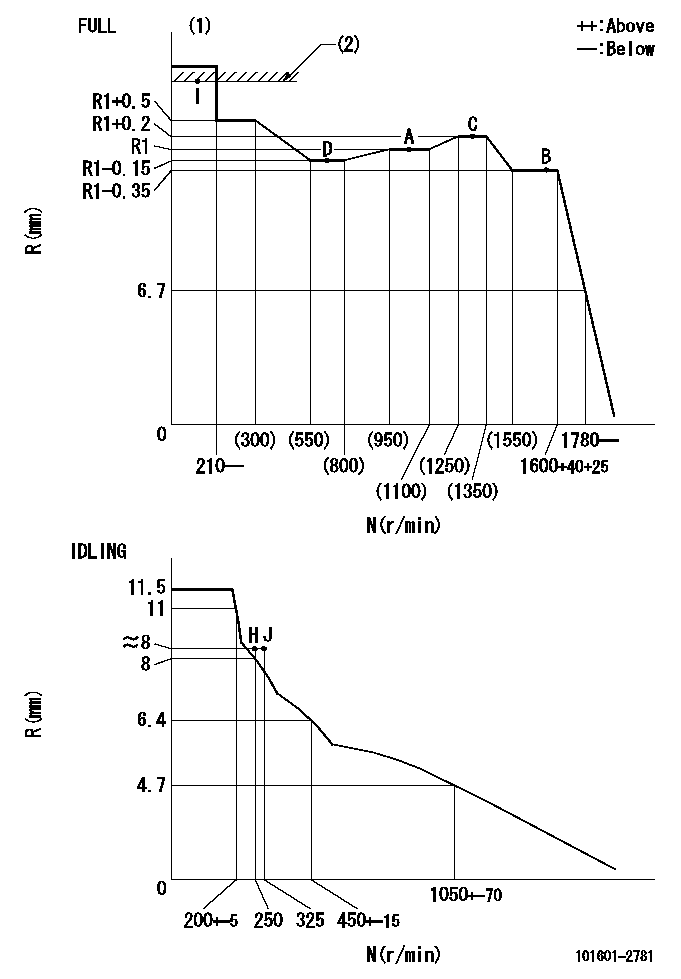
N:Pump speed
R:Rack position (mm)
(1)Torque cam stamping: T1
(2)RACK LIMIT
----------
T1=90
----------
----------
T1=90
----------
Speed control lever angle

F:Full speed
I:Idle
(1)Stopper bolt set position 'H'
----------
----------
a=33deg+-3deg b=34deg+-5deg
----------
----------
a=33deg+-3deg b=34deg+-5deg
Stop lever angle

N:Pump normal
S:Stop the pump.
----------
----------
a=40deg+-5deg b=40deg+-5deg
----------
----------
a=40deg+-5deg b=40deg+-5deg
Timing setting

(1)Pump vertical direction
(2)Position of gear's standard threaded hole at No 1 cylinder's beginning of injection
(3)-
(4)-
----------
----------
a=(70deg)
----------
----------
a=(70deg)
Information:
Exhaust Manifold Removal And Installation
1-Inlet air pipe. 2-Exhaust elbow. 3-Turbocharger oil drain line. 4-Turbocharger oil supply line. 5-Turbocharger. 6-Fuel injection lines (six). 7-Heat shield. 8-Exhaust manifold (three sections).Turbocharger Removal And Installation
Refer to SERVICE GUIDE for Preliminary Information.
1-Exhaust elbow. 2-Turbocharger oil supply line. 3-Bolts and nuts (two each). 4-Bolts, locks and nuts (four each). 5-Turbocharger oil drain line. 6-Inlet air pipe. Apply 9M3710 Anti-Seize Compound to threads of bolts (3 and 4) when installing turbocharger.Turbocharger Disassembly And Assembly
8S9944 Turbine Holder.1,3,5 Remove nut (1). Position the compressor end of housing (5) in an oil bath so only impeller (3) is immersed in oil. Heat impeller to 350° F. (176° C.) for not longer than ten minutes. Remove unit from oil bath and press the shaft and turbine wheel from impeller (3).1,3,5 At installation, heat impeller (3) to a maximum of 350°F. (176°C.) for not longer than ten minutes and proceed as follows: For ease of impeller installation, place the turbine wheel end of center housing (5) in an 8S9944 Turbine Holder.a. Immediately install impeller (3) on shaft, install nut (1) and tighten it to 120 lb. in. (138,4 cm.kg).b. Allow impeller to cool to less than 150°F. (65, 49°C.) and remove nut (1).c. Clean and smooth the washer face of nut (1). Lightly oil the threads of turbine shaft and nut and install the nut.d. Tighten nut (1) to 20 lb. in. (23,0 cm.kg), then tighten an additional 120°.2 Coat threads with 9M3710 Anti-Seize Compound.4,5 Install thrust plate assembly (4) so oil hole aligns with oil hole in housing (5).