Information injection-pump assembly
ZEXEL
101601-2770
1016012770
HINO
220201890A
220201890a

Rating:
Cross reference number
ZEXEL
101601-2770
1016012770
HINO
220201890A
220201890a
Zexel num
Bosch num
Firm num
Name
Calibration Data:
Adjustment conditions
Test oil
1404 Test oil ISO4113 or {SAEJ967d}
1404 Test oil ISO4113 or {SAEJ967d}
Test oil temperature
degC
40
40
45
Nozzle and nozzle holder
105780-8140
Bosch type code
EF8511/9A
Nozzle
105780-0000
Bosch type code
DN12SD12T
Nozzle holder
105780-2080
Bosch type code
EF8511/9
Opening pressure
MPa
17.2
Opening pressure
kgf/cm2
175
Injection pipe
Outer diameter - inner diameter - length (mm) mm 6-2-600
Outer diameter - inner diameter - length (mm) mm 6-2-600
Overflow valve
131424-4220
Overflow valve opening pressure
kPa
162
147
177
Overflow valve opening pressure
kgf/cm2
1.65
1.5
1.8
Tester oil delivery pressure
kPa
157
157
157
Tester oil delivery pressure
kgf/cm2
1.6
1.6
1.6
Direction of rotation (viewed from drive side)
Right R
Right R
Injection timing adjustment
Direction of rotation (viewed from drive side)
Right R
Right R
Injection order
1-4-2-6-
3-5
Pre-stroke
mm
4.9
4.85
4.95
Beginning of injection position
Drive side NO.1
Drive side NO.1
Difference between angles 1
Cal 1-4 deg. 60 59.5 60.5
Cal 1-4 deg. 60 59.5 60.5
Difference between angles 2
Cyl.1-2 deg. 120 119.5 120.5
Cyl.1-2 deg. 120 119.5 120.5
Difference between angles 3
Cal 1-6 deg. 180 179.5 180.5
Cal 1-6 deg. 180 179.5 180.5
Difference between angles 4
Cal 1-3 deg. 240 239.5 240.5
Cal 1-3 deg. 240 239.5 240.5
Difference between angles 5
Cal 1-5 deg. 300 299.5 300.5
Cal 1-5 deg. 300 299.5 300.5
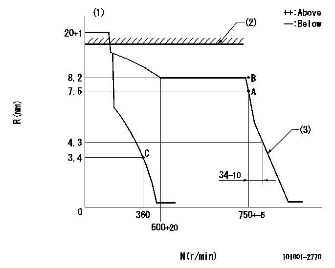
Injection quantity adjustment
Adjusting point
A
Rack position
7.5
Pump speed
r/min
750
750
750
Average injection quantity
mm3/st.
76.9
74.9
78.9
Max. variation between cylinders
%
0
-4
4
Fixing the rack
*
Injection quantity adjustment_02
Adjusting point
B
Rack position
8.2
Pump speed
r/min
750
750
750
Average injection quantity
mm3/st.
84.2
82.6
85.8
Max. variation between cylinders
%
0
-2
2
Basic
*
Fixing the rack
*
Injection quantity adjustment_03
Adjusting point
C
Rack position
4.3+-0.5
Pump speed
r/min
360
360
360
Average injection quantity
mm3/st.
9.5
8
11
Max. variation between cylinders
%
0
-15
15
Fixing the rack
*
Remarks
Adjust only variation between cylinders; adjust governor according to governor specifications.
Adjust only variation between cylinders; adjust governor according to governor specifications.
Timer adjustment
Pump speed
r/min
750
Advance angle
deg.
0
0
0
Remarks
Start
Start
Timer adjustment_02
Pump speed
r/min
-
Advance angle
deg.
3.5
3.5
3.5
Remarks
Finish
Finish
Test data Ex:
Governor adjustment
N:Pump speed
R:Rack position (mm)
(1)Target notch: K
(2)Idle sub spring setting: L1.
(3)RACK LIMIT: RAL
----------
K=18 L1=14+0.2mm RAL=4.5+-0.2mm
----------
----------
K=18 L1=14+0.2mm RAL=4.5+-0.2mm
----------
Speed control lever angle
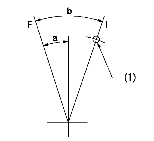
F:Full speed
I:Idle
(1)Stopper bolt setting
----------
----------
a=3deg+-5deg b=20deg+-5deg
----------
----------
a=3deg+-5deg b=20deg+-5deg
Stop lever angle

N:Pump normal
S:Stop the pump.
----------
----------
a=27deg+-5deg b=53deg+-5deg
----------
----------
a=27deg+-5deg b=53deg+-5deg
Timing setting

(1)Pump vertical direction
(2)Coupling's key groove position at No 1 cylinder's beginning of injection
(3)-
(4)-
----------
----------
a=(50deg)
----------
----------
a=(50deg)
Information:
This is a cross section of a hydraulic governor which identifies: 1-Collar. 2-Speed limiter plunger. 3-Lever. 4-Seat. 5-Governor spring. 6-Thrust bearing. 7-Oil passage. 8-Drive gear (weight assembly). 9-Cylinder. 10-Bolt. 11-Spring seat. 12-Weight. 13-Valve. 14-Piston. 15-Sleeve. 16-Oil passage. 17-Fuel rack. The governor valve is shown in the position when the force of the weights and the force of the spring are balanced.When the engine load decreases, the revolving weights speed-up and the toes on the weights move the valve rearward, allowing the oil behind the piston to flow through the drain passage in the center of the valve. At the same time, the pressure oil between the sleeve and the piston forces the piston and rack rearward. This decreases the fuel to the engine and the engine slows down. When the force of the revolving weights balances the governor spring force, the RPM of the engine will be the same as before.When the engine is started, the speed limiter plunger restricts the movement of the accelerator. When operating oil pressure is reached the plunger in the speed limiter retracts and the accelerator can be depressed to the HIGH IDLE position.When the engine RPM is at LOW IDLE, a spring-loaded plunger within the lever assembly in the governor bears against the shoulder of the low idle adjusting screw. To stop the engine, the plunger must be forced past the shoulder on the adjusting screw.Oil from the engine lubricating system lubricates the governor weight bearing. The various other parts are splash lubricated. The oil from the governor drains into the fuel injection pump housing.Fuel Injection Valve
Fuel, under high pressure from the injection pumps, is transferred through the injection lines to the injection valves. As high pressure fuel enters the nozzle assembly, the check valve within the nozzle opens and permits the fuel to enter the precombustion chamber. The injection valve provides the proper spray pattern.
Fuel injection valve cross section. Parts identified are: 1-Fuel line assembly. 2-Seal. 3-Body. 4-Nut. 5-Seal. 6-Nozzle assembly. 7-Glow plug. 8-Precombustion chamber.Lubrication System
This illustration identifies lubrication system components, oil passages and arrows to show the approximate direction of the oil flow in the engine. 1-Oil filter base (includes a bypass valve). 2-Oil passage through the rocker arm shaft. 3-Turbocharger oil reservoir in center section. 4-Oil cooler. 5-Oil cooler bypass valve. 6-Timing gears (in front compartment). 7-Oil pump (in front part of oil pan). 8-Oil filter case. 9-Oil pan (sump). 10-Oil manifold (in engine block assembly).The components in the Lubrication System consists of a sump (oil pan), pump, oil cooler and oil filter. The engine contains an oil manifold and oil passages to direct the oil to the various parts.The pump draws oil from the sump and forces the oil through the oil cooler, oil filter, into the oil manifold. The oil flows through connecting passages to the external and internal engine parts. A regulating valve in the pump body controls the maximum pressure of the oil from the pump.When the engine is started, the lubricating oil in the