Information injection-pump assembly
ZEXEL
101601-2751
1016012751
HINO
220004132A
220004132a

Rating:
Cross reference number
ZEXEL
101601-2751
1016012751
HINO
220004132A
220004132a
Zexel num
Bosch num
Firm num
Name
Calibration Data:
Adjustment conditions
Test oil
1404 Test oil ISO4113 or {SAEJ967d}
1404 Test oil ISO4113 or {SAEJ967d}
Test oil temperature
degC
40
40
45
Nozzle and nozzle holder
105780-8140
Bosch type code
EF8511/9A
Nozzle
105780-0000
Bosch type code
DN12SD12T
Nozzle holder
105780-2080
Bosch type code
EF8511/9
Opening pressure
MPa
17.2
Opening pressure
kgf/cm2
175
Injection pipe
Outer diameter - inner diameter - length (mm) mm 6-2-600
Outer diameter - inner diameter - length (mm) mm 6-2-600
Overflow valve opening pressure
kPa
162
147
177
Overflow valve opening pressure
kgf/cm2
1.65
1.5
1.8
Tester oil delivery pressure
kPa
157
157
157
Tester oil delivery pressure
kgf/cm2
1.6
1.6
1.6
Direction of rotation (viewed from drive side)
Right R
Right R
Injection timing adjustment
Direction of rotation (viewed from drive side)
Right R
Right R
Injection order
1-4-2-6-
3-5
Pre-stroke
mm
3.1
3.07
3.13
Beginning of injection position
Drive side NO.1
Drive side NO.1
Difference between angles 1
Cal 1-4 deg. 60 59.75 60.25
Cal 1-4 deg. 60 59.75 60.25
Difference between angles 2
Cyl.1-2 deg. 120 119.75 120.25
Cyl.1-2 deg. 120 119.75 120.25
Difference between angles 3
Cal 1-6 deg. 180 179.75 180.25
Cal 1-6 deg. 180 179.75 180.25
Difference between angles 4
Cal 1-3 deg. 240 239.75 240.25
Cal 1-3 deg. 240 239.75 240.25
Difference between angles 5
Cal 1-5 deg. 300 299.75 300.25
Cal 1-5 deg. 300 299.75 300.25
Injection quantity adjustment
Adjusting point
A
Rack position
6.9
Pump speed
r/min
900
900
900
Average injection quantity
mm3/st.
65
64
66
Max. variation between cylinders
%
0
-3.5
3.5
Basic
*
Fixing the lever
*
Injection quantity adjustment_02
Adjusting point
B
Rack position
5+-0.5
Pump speed
r/min
375
375
375
Average injection quantity
mm3/st.
8
7
9
Max. variation between cylinders
%
0
-10
10
Fixing the rack
*
Remarks
Adjust only variation between cylinders; adjust governor according to governor specifications.
Adjust only variation between cylinders; adjust governor according to governor specifications.
Injection quantity adjustment_03
Adjusting point
C
Rack position
10.8+-0.
5
Pump speed
r/min
100
100
100
Average injection quantity
mm3/st.
125
125
135
Fixing the lever
*
Rack limit
*
Injection quantity adjustment_04
Adjusting point
E
Rack position
7.2
Pump speed
r/min
600
600
600
Average injection quantity
mm3/st.
56
55
57
Fixing the lever
*
Timer adjustment
Pump speed
r/min
1250
Advance angle
deg.
0.5
Timer adjustment_02
Pump speed
r/min
1300
Advance angle
deg.
1.5
1
2
Timer adjustment_03
Pump speed
r/min
1430
Advance angle
deg.
4.5
4.2
4.8
Remarks
Finish
Finish
Test data Ex:
Governor adjustment
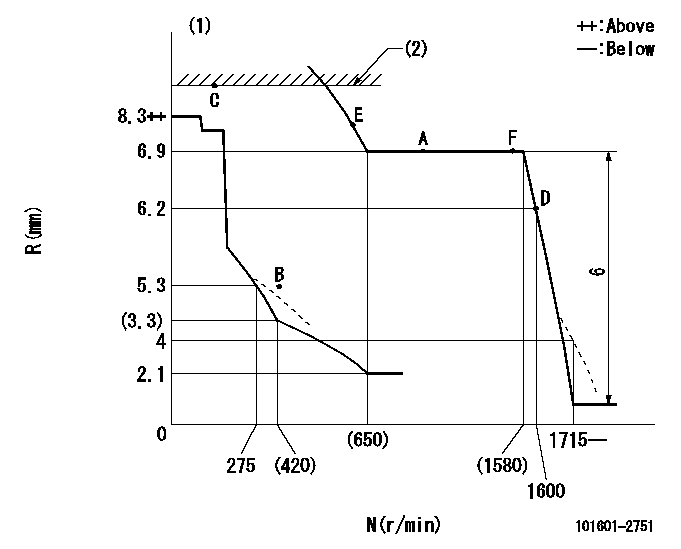
N:Pump speed
R:Rack position (mm)
(1)Beginning of damper spring operation: DL
(2)RACK LIMIT
----------
DL=6-0.2mm
----------
----------
DL=6-0.2mm
----------
Speed control lever angle

F:Full speed
----------
----------
a=21deg+-5deg
----------
----------
a=21deg+-5deg
0000000901

F:Full load
I:Idle
(1)Use the hole at R = aa
(2)Stopper bolt setting
----------
aa=60mm
----------
a=25.5deg+-3deg b=7deg+-5deg
----------
aa=60mm
----------
a=25.5deg+-3deg b=7deg+-5deg
Stop lever angle
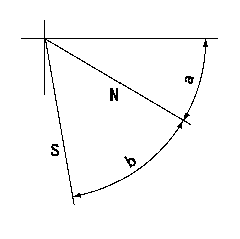
N:Pump normal
S:Stop the pump.
----------
----------
a=35deg+-5deg b=50deg+-5deg
----------
----------
a=35deg+-5deg b=50deg+-5deg
Timing setting

(1)Pump vertical direction
(2)Coupling's key groove position at No 1 cylinder's beginning of injection
(3)-
(4)-
----------
----------
a=(60deg)
----------
----------
a=(60deg)
Information:
1. Remove suction bell (3) and tubes, oil supply tube (2) and BrakeSaver oil supply tube (1) from the engine block and oil pump. 2. Remove three bolts (5) and oil pump (4) from the engine. The following steps are for installation of the oil pump.3. Put oil pump (4) in position on the engine. Make sure the oil pump gear is engaged with the crankshaft gear and install three bolts (5) that hold the oil pump.4. Put clean oil on the O-ring seals on the oil tubes.5. Install suction bell (3) and tubes, oil supply tube (2) and BrakeSaver oil supply tube (1).end by:a) install oil pan (BrakeSaver)Disassemble Oil Pump (Brakesaver)
start by:a) remove oil pump (BrakeSaver) 1. Remove the bolt and washer that hold drive gear (1) on the shaft.2. Use tooling (A) to remove drive gear (1) from the shaft. Remove the key from the shaft. Put marks on the pump bodies so they can be assembled in the correct position. 3. Remove retainer (3) for the bypass valve. Remove the spring and bypass valve.4. Remove bolts (4) that hold pump body (2) to the main pump body. Remove pump body (2).5. Use tooling (B) to remove the bearings from pump body (2). 6. Remove gears (7). Put marks on the gears so they can be assembled in the same position.7. Remove spacer (6) from main oil pump body (5). Use tooling (B) to remove the bearings from spacer (6).8. Remove the gears from main oil pump body (5). 9. Use tooling (B) to remove the bearings from the main oil pump body.Assemble Oil Pump (Brakesaver)
1. Use tooling (A) to install bearings (2) until they are even with the outside surface of main oil pump body (1). Install bearings (2) so the junctions in the bearings are 30° 15° from the center line of the bearing bores and toward the oil pump outlet passage as shown. 2. Use tooling (A) to install bearings (3) in the spacer. Install the bearings until they are in position an equal distance in from each side of the spacer. Install the bearings with the oil holes in the bearings in alignment with the oil holes in the spacer and the junctions in the bearings in alignment with the cavity in the spacer as shown. 3. Put clean engine oil on all the gears and bearings before they are assembled in the oil pump. Install idler and drive gears (5) in the main oil pump body.4. Install spacer (4) on the gear shafts with the smaller cavity out and the oil holes in the spacer toward the pump outlet passage as shown. 5. Use tooling (A) to install bearings (6) in pump body (7) until they are .060 .010 in. (1.52 0.25 mm) from the inside edge of the bearing bores. Install the bearings so the junctions in the bearings are 30° 15° from the center line of the bearing bores and toward the outlet passage. The