Information injection-pump assembly
ZEXEL
101601-2750
1016012750
HINO
220004131B
220004131b

Rating:
Cross reference number
ZEXEL
101601-2750
1016012750
HINO
220004131B
220004131b
Zexel num
Bosch num
Firm num
Name
Calibration Data:
Adjustment conditions
Test oil
1404 Test oil ISO4113 or {SAEJ967d}
1404 Test oil ISO4113 or {SAEJ967d}
Test oil temperature
degC
40
40
45
Nozzle and nozzle holder
105780-8140
Bosch type code
EF8511/9A
Nozzle
105780-0000
Bosch type code
DN12SD12T
Nozzle holder
105780-2080
Bosch type code
EF8511/9
Opening pressure
MPa
17.2
Opening pressure
kgf/cm2
175
Injection pipe
Outer diameter - inner diameter - length (mm) mm 6-2-600
Outer diameter - inner diameter - length (mm) mm 6-2-600
Overflow valve opening pressure
kPa
162
147
177
Overflow valve opening pressure
kgf/cm2
1.65
1.5
1.8
Tester oil delivery pressure
kPa
157
157
157
Tester oil delivery pressure
kgf/cm2
1.6
1.6
1.6
Direction of rotation (viewed from drive side)
Right R
Right R
Injection timing adjustment
Direction of rotation (viewed from drive side)
Right R
Right R
Injection order
1-4-2-6-
3-5
Pre-stroke
mm
3.1
3.07
3.13
Beginning of injection position
Drive side NO.1
Drive side NO.1
Difference between angles 1
Cal 1-4 deg. 60 59.75 60.25
Cal 1-4 deg. 60 59.75 60.25
Difference between angles 2
Cyl.1-2 deg. 120 119.75 120.25
Cyl.1-2 deg. 120 119.75 120.25
Difference between angles 3
Cal 1-6 deg. 180 179.75 180.25
Cal 1-6 deg. 180 179.75 180.25
Difference between angles 4
Cal 1-3 deg. 240 239.75 240.25
Cal 1-3 deg. 240 239.75 240.25
Difference between angles 5
Cal 1-5 deg. 300 299.75 300.25
Cal 1-5 deg. 300 299.75 300.25
Injection quantity adjustment
Adjusting point
A
Rack position
6.9
Pump speed
r/min
900
900
900
Average injection quantity
mm3/st.
65
64
66
Max. variation between cylinders
%
0
-3.5
3.5
Basic
*
Fixing the lever
*
Injection quantity adjustment_02
Adjusting point
B
Rack position
5+-0.5
Pump speed
r/min
375
375
375
Average injection quantity
mm3/st.
8
7
9
Max. variation between cylinders
%
0
-10
10
Fixing the rack
*
Remarks
Adjust only variation between cylinders; adjust governor according to governor specifications.
Adjust only variation between cylinders; adjust governor according to governor specifications.
Injection quantity adjustment_03
Adjusting point
C
Rack position
10.8+-0.
5
Pump speed
r/min
100
100
100
Average injection quantity
mm3/st.
125
125
135
Fixing the lever
*
Injection quantity adjustment_04
Adjusting point
E
Rack position
7.2
Pump speed
r/min
600
600
600
Average injection quantity
mm3/st.
56
55
57
Fixing the lever
*
Rack limit
*
Timer adjustment
Pump speed
r/min
1300--
Advance angle
deg.
0
0
0
Remarks
Start
Start
Timer adjustment_02
Pump speed
r/min
1250
Advance angle
deg.
0.5
Timer adjustment_03
Pump speed
r/min
1300
Advance angle
deg.
1.5
1
2
Timer adjustment_04
Pump speed
r/min
1430
Advance angle
deg.
4.5
4.2
4.8
Remarks
Finish
Finish
Test data Ex:
Governor adjustment
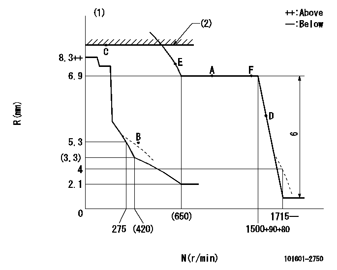
N:Pump speed
R:Rack position (mm)
(1)Beginning of damper spring operation: DL
(2)RACK LIMIT
----------
DL=6-0.2mm
----------
----------
DL=6-0.2mm
----------
Speed control lever angle

F:Full speed
----------
----------
a=22deg+-5deg
----------
----------
a=22deg+-5deg
0000000901

F:Full load
I:Idle
(1)Use the hole at R = aa
(2)Stopper bolt setting
----------
aa=60mm
----------
a=25.5deg+-3deg b=7deg+-5deg
----------
aa=60mm
----------
a=25.5deg+-3deg b=7deg+-5deg
Stop lever angle

N:Pump normal
S:Stop the pump.
----------
----------
a=21deg+-5deg b=69deg+-5deg
----------
----------
a=21deg+-5deg b=69deg+-5deg
Timing setting

(1)Pump vertical direction
(2)Coupling's key groove position at No 1 cylinder's beginning of injection
(3)-
(4)-
----------
----------
a=(60deg)
----------
----------
a=(60deg)
Information:
Remove Brakesaver
start by:a) remove flywheel (BrakeSaver) 1. Disconnect BrakeSaver lubrication oil line (1) from the fitting in the BrakeSaver housing. 2. Disconnect the oil line from fitting (5).3. Remove two short bolts (2) and two longer bolts (4) that hold manifold (3) to the BrakeSaver housing. Remove manifold (3) from the BrakeSaver control valve.4. Remove the O-ring seals from the manifold. The two longer bolts (4) from the manifold can be used as forcing screws to remove the BrakeSaver from the flywheel housing.5. Install a 3/8"-16 NC forged eyebolt in the top of the BrakeSaver housing and fasten a hoist. 6. Install tooling (A) on the BrakeSaver housing and rotor. Tooling (A) holds the BrakeSaver housing and rotor assembly together at removal. This prevents damage to the rotor rings and seals.7. Remove bolts (6) that hold BrakeSaver housing (7) to the flywheel housing.8. Use bolts (4) as forcing screws and tighten the bolts evenly to remove BrakeSaver housing (7) from the flywheel housing. The weight is 190 lb. (86 kg).Install Brakesaver
1. Install tooling (A) on BrakeSaver housing and rotor. Tooling (A) holds the BrakeSaver housing and rotor assembly together at installation. This prevents damage to the rotor rings and seals.2. Install a 3/8"-16 NC forged eyebolt in the top of the BrakeSaver housing and fasten a hoist.3. Install two 5/8"-18 guide pins (3) in the crankshaft as shown. Make sure dowel (2) is in alignment with the dowel hole in the rotor assembly and put BrakeSaver housing (1) in position in the flywheel housing.4. Install the three bolts that hold the BrakeSaver housing to the flywheel housing. Remove tooling (A) and guide pins (3). 5. Connect the oil line to fitting (6).6. Inspect the O-ring seals for damage and make replacements if needed. Install O-ring seals (4) and (5). Put clean oil on the O-ring seals.7. Install manifold (7) into the BrakeSaver control valve and install the four bolts that hold the manifold to the BrakeSaver housing. 8. Connect BrakeSaver lubrication oil line (8) to the fitting in the BrakeSaver housing.end by:a) install flywheel (BrakeSaver)Disassemble Brakesaver
start by:a) remove BrakeSaver1. Remove tooling (A) from the BrakeSaver housing and rotor. Tooling (A) prevents damage to the rotor seals and rings at removal of the BrakeSaver housing. 2. Remove bolts (1) from gear plate (2). Remove the plate. 3. Make identification as to the location of stator (3) with housing (4). Remove bolts (5) and the stator. 4. Turn the stator over and remove spiral ring (6). 5. Turn the stator over again. Remove sleeve assembly (9). Remove O-ring seal (7) and lip type seal (8) from the sleeve. 6. Remove O-ring seal (11) and the six smaller O-ring seals from the oil holes on the housing.7. Remove rotor assembly (12).8. Remove seal ring (10) from both sides of the rotor. 9. Remove carrier (13) and wear sleeve (14) with tooling (B) from both sides of the rotor. 10. Remove spiral ring (15). Turn the housing over and remove sleeve assembly