Information injection-pump assembly
ZEXEL
101601-2741
1016012741
HINO
220004121B
220004121b

Rating:
Cross reference number
ZEXEL
101601-2741
1016012741
HINO
220004121B
220004121b
Zexel num
Bosch num
Firm num
Name
Calibration Data:
Adjustment conditions
Test oil
1404 Test oil ISO4113 or {SAEJ967d}
1404 Test oil ISO4113 or {SAEJ967d}
Test oil temperature
degC
40
40
45
Nozzle and nozzle holder
105780-8140
Bosch type code
EF8511/9A
Nozzle
105780-0000
Bosch type code
DN12SD12T
Nozzle holder
105780-2080
Bosch type code
EF8511/9
Opening pressure
MPa
17.2
Opening pressure
kgf/cm2
175
Injection pipe
Outer diameter - inner diameter - length (mm) mm 6-2-600
Outer diameter - inner diameter - length (mm) mm 6-2-600
Overflow valve opening pressure
kPa
162
147
177
Overflow valve opening pressure
kgf/cm2
1.65
1.5
1.8
Tester oil delivery pressure
kPa
157
157
157
Tester oil delivery pressure
kgf/cm2
1.6
1.6
1.6
Direction of rotation (viewed from drive side)
Right R
Right R
Injection timing adjustment
Direction of rotation (viewed from drive side)
Right R
Right R
Injection order
1-4-2-6-
3-5
Pre-stroke
mm
3.1
3.07
3.13
Beginning of injection position
Drive side NO.1
Drive side NO.1
Difference between angles 1
Cal 1-4 deg. 60 59.75 60.25
Cal 1-4 deg. 60 59.75 60.25
Difference between angles 2
Cyl.1-2 deg. 120 119.75 120.25
Cyl.1-2 deg. 120 119.75 120.25
Difference between angles 3
Cal 1-6 deg. 180 179.75 180.25
Cal 1-6 deg. 180 179.75 180.25
Difference between angles 4
Cal 1-3 deg. 240 239.75 240.25
Cal 1-3 deg. 240 239.75 240.25
Difference between angles 5
Cal 1-5 deg. 300 299.75 300.25
Cal 1-5 deg. 300 299.75 300.25
Injection quantity adjustment
Adjusting point
A
Rack position
6.9
Pump speed
r/min
900
900
900
Average injection quantity
mm3/st.
65
64
66
Max. variation between cylinders
%
0
-3.5
3.5
Basic
*
Fixing the lever
*
Injection quantity adjustment_02
Adjusting point
B
Rack position
5+-0.5
Pump speed
r/min
375
375
375
Average injection quantity
mm3/st.
8
7
9
Max. variation between cylinders
%
0
-10
10
Fixing the rack
*
Remarks
Adjust only variation between cylinders; adjust governor according to governor specifications.
Adjust only variation between cylinders; adjust governor according to governor specifications.
Injection quantity adjustment_03
Adjusting point
C
Rack position
10.8+-0.
5
Pump speed
r/min
100
100
100
Average injection quantity
mm3/st.
125
125
135
Fixing the lever
*
Rack limit
*
Injection quantity adjustment_04
Adjusting point
E
Rack position
7.2
Pump speed
r/min
600
600
600
Average injection quantity
mm3/st.
56
55
57
Fixing the lever
*
Timer adjustment
Pump speed
r/min
1300--
Advance angle
deg.
0
0
0
Remarks
Start
Start
Timer adjustment_02
Pump speed
r/min
1250
Advance angle
deg.
0.5
Timer adjustment_03
Pump speed
r/min
1350
Advance angle
deg.
1.8
1.3
2.3
Timer adjustment_04
Pump speed
r/min
1500
Advance angle
deg.
4.5
4.2
4.8
Remarks
Finish
Finish
Test data Ex:
Governor adjustment
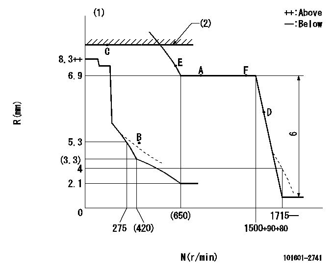
N:Pump speed
R:Rack position (mm)
(1)Beginning of damper spring operation: DL
(2)RACK LIMIT
----------
DL=6-0.2mm
----------
----------
DL=6-0.2mm
----------
Speed control lever angle

F:Full speed
----------
----------
a=22deg+-5deg
----------
----------
a=22deg+-5deg
0000000901

F:Full load
I:Idle
(1)Use the hole at R = aa
(2)Stopper bolt setting
----------
aa=65mm
----------
a=25.5deg+-3deg b=2deg+-5deg
----------
aa=65mm
----------
a=25.5deg+-3deg b=2deg+-5deg
Stop lever angle

N:Pump normal
S:Stop the pump.
----------
----------
a=21deg+-5deg b=69deg+-5deg
----------
----------
a=21deg+-5deg b=69deg+-5deg
Timing setting

(1)Pump vertical direction
(2)Coupling's key groove position at No 1 cylinder's beginning of injection
(3)-
(4)-
----------
----------
a=(60deg)
----------
----------
a=(60deg)
Information:
2. Remove bolt (1) and retainer (2) that hold the oil lines in the BrakeSaver control valve. 3. Disconnect oil lines (3) and (4) from the oil cooler. Remove oil lines (3) and (4) from the BrakeSaver control valve.4. Fasten a hoist to the oil cooler. 5. Remove two bolts (8) to disconnect elbow (10) from front bonnet (9). Remove two bolts (7) to disconnect front bonnet (9) from the water pump.6. Remove four bolts (5) to disconnect the rear bonnet from the cylinder block. Disconnect bracket (12).7. Remove oil cooler (11), front bonnet (9) and rear bonnet (6) from the engine as a unit. The weight is approximately 120 lb. (54 kg).8. Make a separation of front bonnet (9) and rear bonnet (6) from oil cooler (11). 9. Clean oil cooler core tubes (13) with a .150 in. (3.81 mm) diameter rod.Install Oil Cooler (Brakesaver)
1. Inspect all O-ring seals and gaskets for damage and make replacements if needed. Put clean oil on the O-ring seals. 2. Install rear bonnet (1) and front bonnet (3) to oil cooler (2). 3. Fasten a hoist and put the oil cooler and bonnets as a unit in place on the engine. Connect bracket (4) but do not tighten the bolts at this time.4. Install the gasket and four bolts (4) that hold rear bonnet (1) to the engine block. Do not tighten the bolts at this time.5. Install the gasket and two bolts (5) that hold front bonnet (3) to the water pump. Do not tighten the bolts at this time.6. Install the gasket and bolts (6) that hold elbow (7) to the front bonnet. Tighten all the bolts. 7. Make sure the O-ring seals are in place on the oil lines and install oil lines (8) and (9). 8. Install retainer (10) to hold the oil lines in the BrakeSaver control valve. If the bottom plug in the oil pan was removed, put the split (seam) of the gasket for the plug against the oil pan. If either plug on the side of the oil pan was removed, put 5P3413 Thread Sealant on the threads and tighten the plug to a torque of 60 8 lb.ft. (80 11 N m).9. Fill the engine with coolant and oil. See LUBRICATION AND MAINTENANCE GUIDE.
1. Inspect all O-ring seals and gaskets for damage and make replacements if needed. Put clean oil on the O-ring seals. 2. Install rear bonnet (1) and front bonnet (3) to oil cooler (2). 3. Fasten a hoist and put the oil cooler and bonnets as a unit in place on the engine. Connect bracket (4) but do not tighten the bolts at this time.4. Install the gasket and four bolts (4) that hold rear bonnet (1) to the engine block. Do not tighten the bolts at this time.5. Install the gasket and two bolts (5) that hold front bonnet (3) to the water pump. Do not tighten the bolts at this time.6. Install the gasket and bolts (6) that hold elbow (7) to the front bonnet. Tighten all the bolts. 7. Make sure the O-ring seals are in place on the oil lines and install oil lines (8) and (9). 8. Install retainer (10) to hold the oil lines in the BrakeSaver control valve. If the bottom plug in the oil pan was removed, put the split (seam) of the gasket for the plug against the oil pan. If either plug on the side of the oil pan was removed, put 5P3413 Thread Sealant on the threads and tighten the plug to a torque of 60 8 lb.ft. (80 11 N m).9. Fill the engine with coolant and oil. See LUBRICATION AND MAINTENANCE GUIDE.