Information injection-pump assembly
ZEXEL
101601-2711
1016012711
HINO
220201661A
220201661a

Rating:
Cross reference number
ZEXEL
101601-2711
1016012711
HINO
220201661A
220201661a
Zexel num
Bosch num
Firm num
Name
Calibration Data:
Adjustment conditions
Test oil
1404 Test oil ISO4113 or {SAEJ967d}
1404 Test oil ISO4113 or {SAEJ967d}
Test oil temperature
degC
40
40
45
Nozzle and nozzle holder
105780-8140
Bosch type code
EF8511/9A
Nozzle
105780-0000
Bosch type code
DN12SD12T
Nozzle holder
105780-2080
Bosch type code
EF8511/9
Opening pressure
MPa
17.2
Opening pressure
kgf/cm2
175
Injection pipe
Outer diameter - inner diameter - length (mm) mm 6-2-600
Outer diameter - inner diameter - length (mm) mm 6-2-600
Overflow valve opening pressure
kPa
162
147
177
Overflow valve opening pressure
kgf/cm2
1.65
1.5
1.8
Tester oil delivery pressure
kPa
157
157
157
Tester oil delivery pressure
kgf/cm2
1.6
1.6
1.6
Direction of rotation (viewed from drive side)
Right R
Right R
Injection timing adjustment
Direction of rotation (viewed from drive side)
Right R
Right R
Injection order
1-4-2-6-
3-5
Pre-stroke
mm
4.85
4.82
4.88
Beginning of injection position
Drive side NO.1
Drive side NO.1
Difference between angles 1
Cal 1-4 deg. 60 59.75 60.25
Cal 1-4 deg. 60 59.75 60.25
Difference between angles 2
Cyl.1-2 deg. 120 119.75 120.25
Cyl.1-2 deg. 120 119.75 120.25
Difference between angles 3
Cal 1-6 deg. 180 179.75 180.25
Cal 1-6 deg. 180 179.75 180.25
Difference between angles 4
Cal 1-3 deg. 240 239.75 240.25
Cal 1-3 deg. 240 239.75 240.25
Difference between angles 5
Cal 1-5 deg. 300 299.75 300.25
Cal 1-5 deg. 300 299.75 300.25
Injection quantity adjustment
Adjusting point
A
Rack position
9.8
Pump speed
r/min
800
800
800
Average injection quantity
mm3/st.
86.9
85.3
88.5
Max. variation between cylinders
%
0
-2
2
Basic
*
Fixing the lever
*
Injection quantity adjustment_02
Adjusting point
B
Rack position
6.2+-0.5
Pump speed
r/min
310
310
310
Average injection quantity
mm3/st.
10
8.5
11.5
Max. variation between cylinders
%
0
-15
15
Fixing the rack
*
Injection quantity adjustment_03
Adjusting point
D
Rack position
10.4
Pump speed
r/min
1400
1400
1400
Average injection quantity
mm3/st.
105.8
100.6
111
Max. variation between cylinders
%
0
-3
3
Fixing the lever
*
Timer adjustment
Pump speed
r/min
1200
Advance angle
deg.
0.5
Timer adjustment_02
Pump speed
r/min
1300
Advance angle
deg.
1.4
0.9
1.9
Timer adjustment_03
Pump speed
r/min
1400
Advance angle
deg.
3.3
2.8
3.8
Timer adjustment_04
Pump speed
r/min
-
Advance angle
deg.
4.5
4.2
4.8
Remarks
Measure the actual speed, stop
Measure the actual speed, stop
Test data Ex:
Governor adjustment
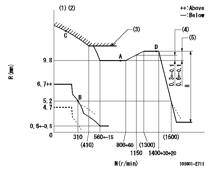
N:Pump speed
R:Rack position (mm)
(1)Set the load lever's stop position so that R = aa (N = 0).
(2)Beginning of damper spring operation: DL
(3)Excess fuel setting for starting: SXL
(4)Rack difference between N = N1 and N = N2
(5)Rack difference between N = N3 and N = N4
----------
aa=4.7mm DL=4.3-0.5mm SXL=10.4+0.2mm N1=1150r/min N2=800r/min N3=1400r/min N4=800r/min
----------
----------
aa=4.7mm DL=4.3-0.5mm SXL=10.4+0.2mm N1=1150r/min N2=800r/min N3=1400r/min N4=800r/min
----------
Speed control lever angle

F:Full speed
----------
----------
a=9deg+-5deg
----------
----------
a=9deg+-5deg
0000000901
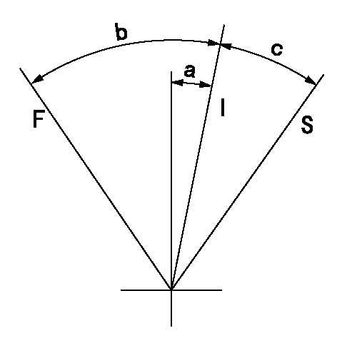
F:Full load
I:Idle
S:Stop
----------
----------
a=18deg+-5deg b=34deg+-3deg c=16deg+-5deg
----------
----------
a=18deg+-5deg b=34deg+-3deg c=16deg+-5deg
Information:
start by: a) remove oil pump1. Check the connecting rods and caps for their identification and location.2. Turn crankshaft until connecting rod caps are in position shown. 3. Remove the nuts (1) and the cap from connecting rod. Remove lower half of bearing from cap.4. Push the connecting rod away from the crankshaft. Remove the upper half of bearing from connecting rod. Install the bearings dry when the clearance checks are made. Put clean engine oil on the bearings for final assembly.5. Install upper half of bearing in connecting rod.6. Pull the connecting rod slowly on to the crankshaft.7. Install lower half of bearing in cap. Be sure the tabs in back of bearings are in the tab grooves of connecting rod and cap.
Do not use an impact wrench to tighten the bolts the additional 120° 5°.
8. Use Plastigage (A) to check bearing clearance.9. Put Plastigage (A) on the bearing.10. Put clean engine oil on threads of rod bolts and seat surfaces of nuts. Be sure the cylinder numbers on the rod cap and rod are the same and are on the same side of the connecting rod. Numbers are on the same side of rod and caps as are the grooves for the bearing tabs. If new rods are installed, put the cylinder number on the rod and cap. Do not turn the crankshaft when Plastigage (A) is in position. 11. Install the rod caps (2). Install the nuts. Tighten each nut to a torque of 60 6 lb. ft. (80 8 N m). Put a mark on the nuts and cap and tighten nuts an extra 120° 5° from the mark. Remove the rod cap. Remove Plastigage (A) and check the bearing clearance. The bearing clearance must be .0028 to .0066 in. (0.071 to 0.168 mm) for new bearings. Maximum clearance with used bearings is .010 in. (0.25 mm).12. Put clean engine oil on lower half of bearing. Install rod cap again. Tighten each nut to 60 6 lb.ft. (80 8 N m). Put a mark on nuts and cap and tighten nuts an extra 120° 5° from mark.13. Do Steps 1 through 12 for remainder of connecting rod bearings.end by:a) install oil pump