Information injection-pump assembly
ZEXEL
101601-2590
1016012590
HINO
220003491A
220003491a
Rating:
Service parts 101601-2590 INJECTION-PUMP ASSEMBLY:
1.
_
2.
FUEL INJECTION PUMP
7.
COUPLING PLATE
8.
_
9.
_
11.
Nozzle and Holder
23600-1171
12.
Open Pre:MPa(Kqf/cm2)
18.1{185}

15.
NOZZLE SET
Cross reference number
ZEXEL
101601-2590
1016012590
HINO
220003491A
220003491a
Zexel num
Bosch num
Firm num
Name
Calibration Data:
Adjustment conditions
Test oil
1404 Test oil ISO4113 or {SAEJ967d}
1404 Test oil ISO4113 or {SAEJ967d}
Test oil temperature
degC
40
40
45
Nozzle and nozzle holder
105780-8140
Bosch type code
EF8511/9A
Nozzle
105780-0000
Bosch type code
DN12SD12T
Nozzle holder
105780-2080
Bosch type code
EF8511/9
Opening pressure
MPa
17.2
Opening pressure
kgf/cm2
175
Injection pipe
Outer diameter - inner diameter - length (mm) mm 6-2-600
Outer diameter - inner diameter - length (mm) mm 6-2-600
Overflow valve
134424-0620
Overflow valve opening pressure
kPa
162
147
177
Overflow valve opening pressure
kgf/cm2
1.65
1.5
1.8
Tester oil delivery pressure
kPa
157
157
157
Tester oil delivery pressure
kgf/cm2
1.6
1.6
1.6
Direction of rotation (viewed from drive side)
Right R
Right R
Injection timing adjustment
Direction of rotation (viewed from drive side)
Right R
Right R
Injection order
1-4-2-6-
3-5
Pre-stroke
mm
4.85
4.82
4.88
Beginning of injection position
Drive side NO.1
Drive side NO.1
Difference between angles 1
Cal 1-4 deg. 60 59.75 60.25
Cal 1-4 deg. 60 59.75 60.25
Difference between angles 2
Cyl.1-2 deg. 120 119.75 120.25
Cyl.1-2 deg. 120 119.75 120.25
Difference between angles 3
Cal 1-6 deg. 180 179.75 180.25
Cal 1-6 deg. 180 179.75 180.25
Difference between angles 4
Cal 1-3 deg. 240 239.75 240.25
Cal 1-3 deg. 240 239.75 240.25
Difference between angles 5
Cal 1-5 deg. 300 299.75 300.25
Cal 1-5 deg. 300 299.75 300.25
Injection quantity adjustment
Adjusting point
B
Rack position
9
Pump speed
r/min
850
850
850
Average injection quantity
mm3/st.
86.7
85.1
88.3
Max. variation between cylinders
%
0
-2
2
Basic
*
Fixing the lever
*
Injection quantity adjustment_02
Adjusting point
C
Rack position
9.7
Pump speed
r/min
1450
1450
1450
Average injection quantity
mm3/st.
100.7
98.1
103.3
Max. variation between cylinders
%
0
-3
3
Fixing the lever
*
Injection quantity adjustment_03
Adjusting point
D
Rack position
4.9
Pump speed
r/min
250
250
250
Average injection quantity
mm3/st.
6
4.5
7.5
Max. variation between cylinders
%
0
-15
15
Fixing the rack
*
Injection quantity adjustment_04
Adjusting point
E
Rack position
11.4+-0.
5
Pump speed
r/min
100
100
100
Average injection quantity
mm3/st.
78
78
98
Fixing the lever
*
Remarks
After startup boost setting
After startup boost setting
Timer adjustment
Pump speed
r/min
1200
Advance angle
deg.
0.5
Timer adjustment_02
Pump speed
r/min
1300
Advance angle
deg.
1.4
0.9
1.9
Timer adjustment_03
Pump speed
r/min
1450
Advance angle
deg.
4.5
4.2
4.8
Remarks
Finish
Finish
Test data Ex:
Governor adjustment
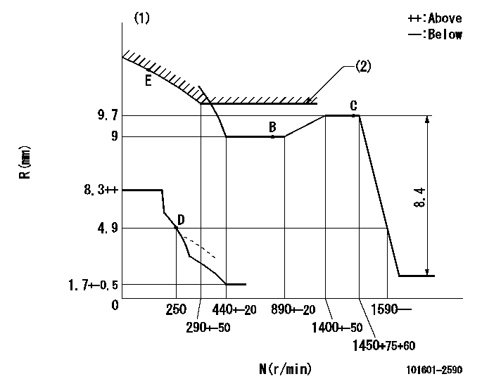
N:Pump speed
R:Rack position (mm)
(1)Beginning of damper spring operation: DL
(2)Excess fuel setting for starting: SXL
----------
DL=4-0.5mm SXL=9.7+0.2mm
----------
----------
DL=4-0.5mm SXL=9.7+0.2mm
----------
Speed control lever angle

F:Full speed
----------
----------
a=12deg+-5deg
----------
----------
a=12deg+-5deg
0000000901

F:Full load
I:Idle
(1)Stopper bolt setting
----------
----------
a=18deg+-5deg b=27deg+-3deg
----------
----------
a=18deg+-5deg b=27deg+-3deg
Stop lever angle

N:Pump normal
S:Stop the pump.
----------
----------
a=21deg+-5deg b=69deg+-5deg
----------
----------
a=21deg+-5deg b=69deg+-5deg
0000001501 MICRO SWITCH
Switch adjustment
Adjust the bolt so that the lower lever position is obtained when the switch is turned ON.
(1)Speed N1
(2)Rack position Ra
----------
N1=350+25r/min Ra=4.9mm
----------
----------
N1=350+25r/min Ra=4.9mm
----------
Information:
Engine Runs Rough
10. Misfiring Cylinder(s) ... See Misfiring and Running Rough.11. Fuel Injection Timing Not Correct ... Check and make necessary adjustments as per Testing and Adjusting section of this Service Manual.12. Automatic Timing Advance Does Not Operate Correctly ... Check with engine warm. Use the 1P3500 Timing Light Group. Special Instruction Form No. SMHS6964 gives the test procedure. If the timing light is not available, make rapid "acceleration" (increase in speed) from low idle to high idle. Engine must have smooth acceleration. A timing advance that does not operate correctly can cause delays of the engine acceleration at some rpm before high idle, or possibly cause the engine to run rough and have exhaust noise (backfire) during acceleration. This condition is difficult to find if engine acceleration is slow or at a constant engine rpm. 13. Air in Fuel System ... With air in the fuel system, the engine will normally be difficult to start, run rough, and release a large amount of white smoke. If the engine will not start, loosen a fuel injection line nut at the valve cover base. With the governor lever in the shutoff position, operate the fuel priming pump until the flow of fuel from the loosened fuel injection line is free of air. Tighten the fuel line nut. Fasten the priming pump and start the engine. If the engine still does not run smooth or releases a large amount of white smoke, loosen the fuel line nuts one at a time at the valve cover base until the fuel that comes out is free of air. Tighten the fuel line nuts. If the air can not be removed in this way, put 5 psi (35 kPa) of air pressure to the fuel tank.
Do not use more than 8 psi (55 kPa) of air pressure in the fuel tank or damage to the tank may result.
Check for leakage at the connections between the fuel tank and the fuel transfer pump. If leaks are found, tighten the connections or replace the lines. If there are no visual leaks, remove the fuel supply line from the tank and connect it to an outside fuel supply. If this corrects the problem, the suction line (standpipe) inside the fuel tank has a leak. White Smoke Recommended Procedure
1. Cold Outside Temperatures ... When the air outside is cold, the cylinder temperature is cooler. Not all the fuel will burn in the cylinders. The fuel which does not burn comes out the exhaust as white smoke. White smoke is normal in cold temperatures until the engine operates long enough to become warm. There will be less white smoke if No. 1 diesel fuel is used.2. Long Idle Periods ... When an engine runs at idle speed for a long period of time, the cylinders cool and all of the fuel does not burn. Do not idle an engine for a long period of time. Stop an engine when it is not in use. If long idle