Information injection-pump assembly
ZEXEL
101601-2550
1016012550
HINO
220801090A
220801090a

Rating:
Cross reference number
ZEXEL
101601-2550
1016012550
HINO
220801090A
220801090a
Zexel num
Bosch num
Firm num
Name
Calibration Data:
Adjustment conditions
Test oil
1404 Test oil ISO4113 or {SAEJ967d}
1404 Test oil ISO4113 or {SAEJ967d}
Test oil temperature
degC
40
40
45
Nozzle and nozzle holder
105780-8140
Bosch type code
EF8511/9A
Nozzle
105780-0000
Bosch type code
DN12SD12T
Nozzle holder
105780-2080
Bosch type code
EF8511/9
Opening pressure
MPa
17.2
Opening pressure
kgf/cm2
175
Injection pipe
Outer diameter - inner diameter - length (mm) mm 6-2-600
Outer diameter - inner diameter - length (mm) mm 6-2-600
Overflow valve
134424-0920
Overflow valve opening pressure
kPa
162
147
177
Overflow valve opening pressure
kgf/cm2
1.65
1.5
1.8
Tester oil delivery pressure
kPa
157
157
157
Tester oil delivery pressure
kgf/cm2
1.6
1.6
1.6
Direction of rotation (viewed from drive side)
Right R
Right R
Injection timing adjustment
Direction of rotation (viewed from drive side)
Right R
Right R
Injection order
1-4-2-6-
3-5
Pre-stroke
mm
3.1
3.07
3.13
Beginning of injection position
Drive side NO.1
Drive side NO.1
Difference between angles 1
Cal 1-4 deg. 60 59.75 60.25
Cal 1-4 deg. 60 59.75 60.25
Difference between angles 2
Cyl.1-2 deg. 120 119.75 120.25
Cyl.1-2 deg. 120 119.75 120.25
Difference between angles 3
Cal 1-6 deg. 180 179.75 180.25
Cal 1-6 deg. 180 179.75 180.25
Difference between angles 4
Cal 1-3 deg. 240 239.75 240.25
Cal 1-3 deg. 240 239.75 240.25
Difference between angles 5
Cal 1-5 deg. 300 299.75 300.25
Cal 1-5 deg. 300 299.75 300.25
Injection quantity adjustment
Adjusting point
A
Rack position
6.6
Pump speed
r/min
1000
1000
1000
Average injection quantity
mm3/st.
65.6
64.6
66.6
Max. variation between cylinders
%
0
-3.5
3.5
Basic
*
Fixing the lever
*
Injection quantity adjustment_02
Adjusting point
B
Rack position
6.6
Pump speed
r/min
1500
1500
1500
Average injection quantity
mm3/st.
65.5
64
67
Max. variation between cylinders
%
0
-5
5
Fixing the lever
*
Injection quantity adjustment_03
Adjusting point
C
Rack position
5.2+-0.5
Pump speed
r/min
375
375
375
Average injection quantity
mm3/st.
8
7
9
Max. variation between cylinders
%
0
-10
10
Fixing the rack
*
Remarks
Adjust only variation between cylinders; adjust governor according to governor specifications.
Adjust only variation between cylinders; adjust governor according to governor specifications.
Timer adjustment
Pump speed
r/min
1350
Advance angle
deg.
0.5
Timer adjustment_02
Pump speed
r/min
1400
Advance angle
deg.
1.5
Timer adjustment_03
Pump speed
r/min
1600
Advance angle
deg.
5
4.7
5.3
Remarks
Finish
Finish
Test data Ex:
Governor adjustment
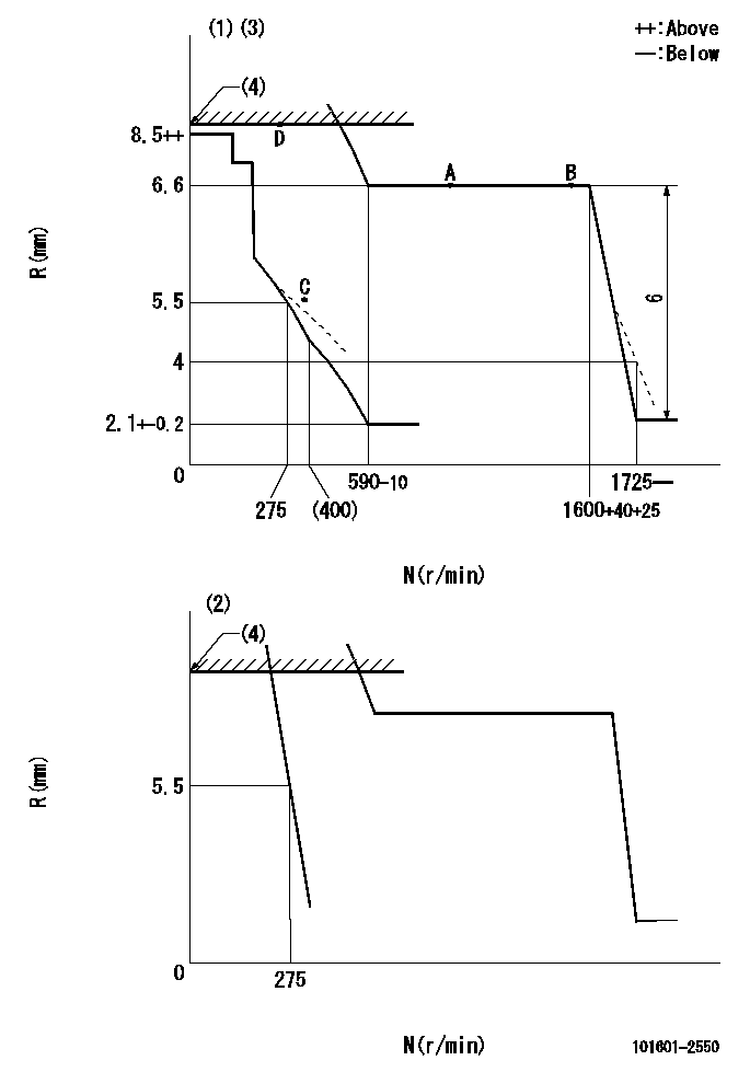
N:Pump speed
R:Rack position (mm)
(1)Minimum - maximum speed specification
(2)Variable speed specification.
(3)Beginning of damper spring operation: DL
(4)RACK LIMIT: RAL
----------
DL=5.7-0.2mm RAL=9.8+0.2mm
----------
----------
DL=5.7-0.2mm RAL=9.8+0.2mm
----------
Speed control lever angle
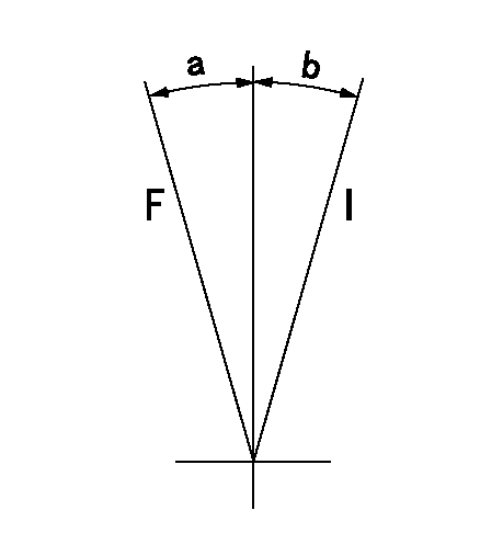
F:Full speed
I:Idle
----------
----------
a=15deg+-5deg b=11deg+-5deg
----------
----------
a=15deg+-5deg b=11deg+-5deg
0000000901

F:Full load
I:Idle
(1)Stopper bolt setting
----------
----------
a=2deg+-5deg b=26deg+-3deg
----------
----------
a=2deg+-5deg b=26deg+-3deg
Stop lever angle

N:Pump normal
S:Stop the pump.
----------
----------
a=21deg+-5deg b=69deg+-5deg
----------
----------
a=21deg+-5deg b=69deg+-5deg
0000001201
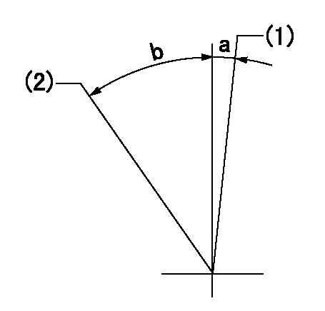
(1)Variable speed specification
(2)Minimum - maximum speed specification
----------
----------
a=3deg+-5deg b=39.5deg+-6deg
----------
----------
a=3deg+-5deg b=39.5deg+-6deg
0000001501 MICRO SWITCH
Switch adjustment
Adjust the bolt so that the lower lever position is obtained when the switch is turned ON.
(1)Speed N1
(2)Rack position Ra
----------
N1=375-25r/min Ra=5.5mm
----------
----------
N1=375-25r/min Ra=5.5mm
----------
Information:
Charging System
5P300 Electrical Tester. Make reference to Special Instruction Form No. GEG02276, and to the instructions inside of the cover of the tester, when testing with the 5P300 Electrical Tester.The condition of charge in the battery at each regular inspection will show if the charging system operates correctly. An adjustment is necessary when the battery is constantly in a low condition of charge or a large amount of water is needed (more than one ounce of water per cell per week or per every 50 service hours).Make a test of the charging unit and voltage regulator on the engine, when possible, using wiring and components that are a permanent part of the system. Off-engine (bench) testing will give a test of the charging unit and voltage regulator operation. This testing will give an indication of needed repair. After repairs are made, again make a test to give proof that the units are repaired to their original condition of operation.Before the start of on-engine testing, the charging system and battery must be checked as shown in the Steps that follow:1. Battery must be at least 75% (1.240 Sp. Gr.) fully charged and held tightly in place. The battery holder must not put too much stress on the battery.2. Cables between the battery, starter and engine ground must be the correct size. Wires and cables must be free of corrosion and have cable support clamps to prevent stress on battery connections (terminals).3. Leads, junctions, switches and panel instruments that have direct relation to the charging circuit must give correct circuit control.4. Inspect the drive components for the charging unit to be sure they are free of grease and oil and have the ability to operate the charging unit.Alternator Regulator Adjustment
When an alternator is charging the battery too much or not enough, an adjustment can be made to the charging rate of the alternator.To make an adjustment to the voltage output on these alternators, remove the voltage adjustment cap (1) from the alternator, turn the cap 90°, and install it again into the alternator. The voltage adjustment cap has four positions: HI, LO, and two positions between the high and the low setting.
ALTERNATOR REGULATOR ADJUSTMENT
1. Voltage adjustment cap.Delco-Remy Alternator; Pulley Nut Tightening
Tighten nut that holds the pulley to a torque of 75 5 lb. ft. (100 7 N m) with the tools shown.
ALTERNATOR PULLEY INSTALLATION
1. 8S1588 Adapter (1/2" female to 3/8" male). 2. 8S1590 Socket (5/16" with 3/8" drive). 3. 1P2977 Tool Group. 8H8555 Socket (15/16" with 1/2" drive) not shown.Starting System
5P300 Electrical Tester. Make reference to Special Instruction Form No. GEG02276, and to the instructions inside of the cover of the tester, when the 5P300 Electrical Tester is used.Use a D.C. Voltmeter to find starting system components which do not function.Move the start control switch to activate the starter solenoid. Starter solenoid operation can be heard as the pinion of the starter motor is engaged with the ring gear on the engine flywheel.If the solenoid for the starter