Information injection-pump assembly
ZEXEL
101601-2510
1016012510
HINO
220002390A
220002390a

Rating:
Cross reference number
ZEXEL
101601-2510
1016012510
HINO
220002390A
220002390a
Zexel num
Bosch num
Firm num
Name
Calibration Data:
Adjustment conditions
Test oil
1404 Test oil ISO4113 or {SAEJ967d}
1404 Test oil ISO4113 or {SAEJ967d}
Test oil temperature
degC
40
40
45
Nozzle and nozzle holder
105780-8140
Bosch type code
EF8511/9A
Nozzle
105780-0000
Bosch type code
DN12SD12T
Nozzle holder
105780-2080
Bosch type code
EF8511/9
Opening pressure
MPa
17.2
Opening pressure
kgf/cm2
175
Injection pipe
Outer diameter - inner diameter - length (mm) mm 6-2-600
Outer diameter - inner diameter - length (mm) mm 6-2-600
Overflow valve
134424-0620
Overflow valve opening pressure
kPa
162
147
177
Overflow valve opening pressure
kgf/cm2
1.65
1.5
1.8
Tester oil delivery pressure
kPa
157
157
157
Tester oil delivery pressure
kgf/cm2
1.6
1.6
1.6
Direction of rotation (viewed from drive side)
Right R
Right R
Injection timing adjustment
Direction of rotation (viewed from drive side)
Right R
Right R
Injection order
1-4-2-6-
3-5
Pre-stroke
mm
4.85
4.8
4.9
Beginning of injection position
Drive side NO.1
Drive side NO.1
Difference between angles 1
Cal 1-4 deg. 60 59.5 60.5
Cal 1-4 deg. 60 59.5 60.5
Difference between angles 2
Cyl.1-2 deg. 120 119.5 120.5
Cyl.1-2 deg. 120 119.5 120.5
Difference between angles 3
Cal 1-6 deg. 180 179.5 180.5
Cal 1-6 deg. 180 179.5 180.5
Difference between angles 4
Cal 1-3 deg. 240 239.5 240.5
Cal 1-3 deg. 240 239.5 240.5
Difference between angles 5
Cal 1-5 deg. 300 299.5 300.5
Cal 1-5 deg. 300 299.5 300.5
Injection quantity adjustment
Adjusting point
A
Rack position
9
Pump speed
r/min
600
600
600
Average injection quantity
mm3/st.
78.3
75.9
80.7
Max. variation between cylinders
%
0
-3
3
Fixing the lever
*
Injection quantity adjustment_02
Adjusting point
B
Rack position
9
Pump speed
r/min
850
850
850
Average injection quantity
mm3/st.
86.7
85.1
88.3
Max. variation between cylinders
%
0
-2
2
Basic
*
Fixing the lever
*
Injection quantity adjustment_03
Adjusting point
C
Rack position
9.7
Pump speed
r/min
1450
1450
1450
Average injection quantity
mm3/st.
100.7
98.1
103.3
Max. variation between cylinders
%
0
-3
3
Fixing the lever
*
Injection quantity adjustment_04
Adjusting point
D
Rack position
4.9+-0.5
Pump speed
r/min
250
250
250
Average injection quantity
mm3/st.
6
4.5
7.5
Max. variation between cylinders
%
0
-15
15
Fixing the rack
*
Injection quantity adjustment_05
Adjusting point
E
Rack position
10
Pump speed
r/min
1450
1450
1450
Average injection quantity
mm3/st.
101
99.4
102.6
Fixing the rack
*
Timer adjustment
Pump speed
r/min
1150+-50
Advance angle
deg.
0
0
0
Remarks
Start
Start
Timer adjustment_02
Pump speed
r/min
1300
Advance angle
deg.
1.9
1.4
2.4
Timer adjustment_03
Pump speed
r/min
1400
Advance angle
deg.
3.5
3
4
Remarks
Finish
Finish
Test data Ex:
Governor adjustment
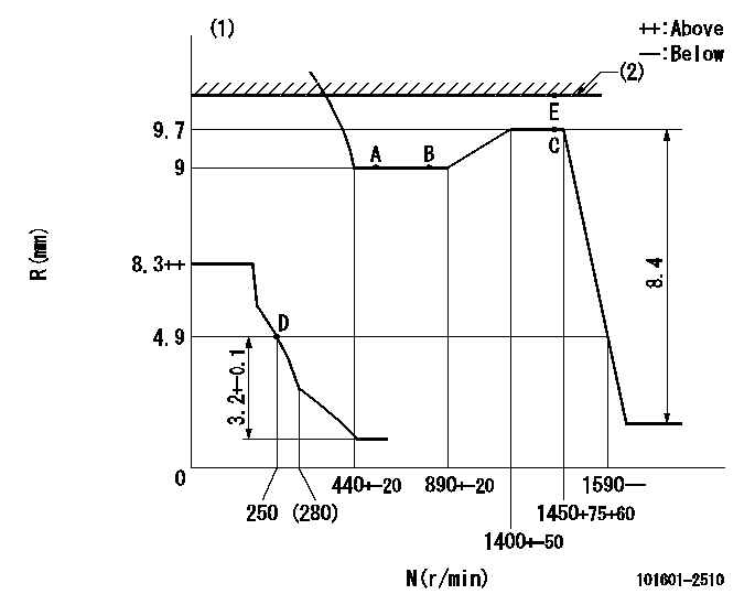
N:Pump speed
R:Rack position (mm)
(1)Beginning of damper spring operation: DL
(2)RACK LIMIT
----------
DL=4-0.5mm
----------
----------
DL=4-0.5mm
----------
Speed control lever angle

F:Full speed
----------
----------
a=11deg+-5deg
----------
----------
a=11deg+-5deg
0000000901

F:Full load
I:Idle
(1)Stopper bolt setting
----------
----------
a=18deg+-5deg b=27deg+-3deg
----------
----------
a=18deg+-5deg b=27deg+-3deg
Stop lever angle

N:Pump normal
S:Stop the pump.
----------
----------
a=21deg+-5deg b=69deg+-5deg
----------
----------
a=21deg+-5deg b=69deg+-5deg
0000001501 MICRO SWITCH
Switch adjustment
Adjust the bolt so that the lower lever position is obtained when the switch is turned ON.
(1)Speed N1
(2)Rack position Ra
----------
N1=350+25r/min Ra=4.9mm
----------
----------
N1=350+25r/min Ra=4.9mm
----------
Information:
Camshaft rotation counterclockwise in view shown.Firing order (injection sequence) ... 1, 5, 3, 6, 2, 4Injection timing before TC (top center):Precombustion Chamber (PC) ... 10 1°*Direct Injection (DI) ... 29 1°*Direct Injection (DI) ... 28 1°*Direct Injection (DI) ... 26.5 1°*Direct Injection (DI) ... 22.5 1°*Make reference to DI FUEL SYSTEM CHART in FUEL SYSTEM IDENTIFICATION section to find correct injection pump groups.(1) Torque for bushing ... 150 10 lb. ft.(205 14 N m)
A - 8S7167 GAUGE
B - 5P4158 GAUGE (5) Bore for the rack and diameter of the rack: Bearing at the rear (new) ... .5018 .0018 in.(12.746 0.046 mm)Bearing at the front (new) ... .5023 .0018 in.(12.758 0.046 mm)Diameter of fuel rack (new) ... .4985 .0002 in.(12.662 0.005 mm)Maximum permissible clearance between rack and bearings (worn) ... .007 in.(0.18 mm)(6) Bore in bearings for the camshaft (new) ... 2.1255 .0015 in.(53.988 0.038 mm) Diameter of bearing surfaces of the camshaft (new) ... 2.1220 .0005 in.(53.899 0.013 mm)Maximum permissible clearance between the bearings and the camshaft ... .010 in.(0.25 mm)
PRECHAMBER(9) Torque for all nuts that hold the fuel lines ... 30 5 lb. ft.(40 7 N m)(10) Torque for the nuts that hold the nozzles ... 55 5 lb. ft.(75 7 N m)(11) Body.
DIRECT INJECTION(12) Nozzle. Tighten nozzle finger tight on body (11).(13) Torque for precombustion chamber or direct injection adapter ... 150 10 lb. ft.(205 14 N m)(14) Torque for glow plug ... 120 24 lb. in.(13.6 2.8 N m)