Information injection-pump assembly
ZEXEL
101601-2290
1016012290
HINO
220001350B
220001350b

Rating:
Cross reference number
ZEXEL
101601-2290
1016012290
HINO
220001350B
220001350b
Zexel num
Bosch num
Firm num
Name
Calibration Data:
Adjustment conditions
Test oil
1404 Test oil ISO4113 or {SAEJ967d}
1404 Test oil ISO4113 or {SAEJ967d}
Test oil temperature
degC
40
40
45
Nozzle and nozzle holder
105780-8140
Bosch type code
EF8511/9A
Nozzle
105780-0000
Bosch type code
DN12SD12T
Nozzle holder
105780-2080
Bosch type code
EF8511/9
Opening pressure
MPa
17.2
Opening pressure
kgf/cm2
175
Injection pipe
Outer diameter - inner diameter - length (mm) mm 6-2-600
Outer diameter - inner diameter - length (mm) mm 6-2-600
Overflow valve
131424-2220
Overflow valve opening pressure
kPa
123
103
143
Overflow valve opening pressure
kgf/cm2
1.25
1.05
1.45
Tester oil delivery pressure
kPa
157
157
157
Tester oil delivery pressure
kgf/cm2
1.6
1.6
1.6
Direction of rotation (viewed from drive side)
Right R
Right R
Injection timing adjustment
Direction of rotation (viewed from drive side)
Right R
Right R
Injection order
1-4-2-6-
3-5
Pre-stroke
mm
1.9
1.85
1.95
Beginning of injection position
Drive side NO.1
Drive side NO.1
Difference between angles 1
Cal 1-4 deg. 60 59.5 60.5
Cal 1-4 deg. 60 59.5 60.5
Difference between angles 2
Cyl.1-2 deg. 120 119.5 120.5
Cyl.1-2 deg. 120 119.5 120.5
Difference between angles 3
Cal 1-6 deg. 180 179.5 180.5
Cal 1-6 deg. 180 179.5 180.5
Difference between angles 4
Cal 1-3 deg. 240 239.5 240.5
Cal 1-3 deg. 240 239.5 240.5
Difference between angles 5
Cal 1-5 deg. 300 299.5 300.5
Cal 1-5 deg. 300 299.5 300.5
Injection quantity adjustment
Adjusting point
A
Rack position
12.5
Pump speed
r/min
500
500
500
Average injection quantity
mm3/st.
122
119
125
Max. variation between cylinders
%
0
-4
4
Fixing the lever
*
Injection quantity adjustment_02
Adjusting point
B
Rack position
12.8
Pump speed
r/min
600
600
600
Average injection quantity
mm3/st.
125
123
127
Max. variation between cylinders
%
0
-4
4
Fixing the lever
*
Injection quantity adjustment_03
Adjusting point
C
Rack position
12.8
Pump speed
r/min
800
800
800
Average injection quantity
mm3/st.
129.7
127.7
131.7
Max. variation between cylinders
%
0
-2
2
Basic
*
Fixing the lever
*
Injection quantity adjustment_04
Adjusting point
D
Rack position
13.1
Pump speed
r/min
1125
1125
1125
Average injection quantity
mm3/st.
135.5
132.5
138.5
Max. variation between cylinders
%
0
-4
4
Fixing the lever
*
Injection quantity adjustment_05
Adjusting point
E
Rack position
7.1+-0.5
Pump speed
r/min
225
225
225
Average injection quantity
mm3/st.
23
20
26
Max. variation between cylinders
%
0
-13
13
Fixing the rack
*
Injection quantity adjustment_06
Adjusting point
F
Rack position
15.5++
Pump speed
r/min
50
50
50
Average injection quantity
mm3/st.
140
140
Fixing the lever
*
Remarks
After startup boost setting
After startup boost setting
Timer adjustment
Pump speed
r/min
450+-50
Advance angle
deg.
0
0
0
Remarks
Start
Start
Timer adjustment_02
Pump speed
r/min
600
Advance angle
deg.
1.3
0.8
1.8
Timer adjustment_03
Pump speed
r/min
800
Advance angle
deg.
3.3
2.8
3.8
Timer adjustment_04
Pump speed
r/min
1000
Advance angle
deg.
5.7
5.2
6.2
Timer adjustment_05
Pump speed
r/min
1150
Advance angle
deg.
8
7.5
8.5
Remarks
Finish
Finish
Test data Ex:
Governor adjustment
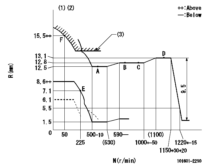
N:Pump speed
R:Rack position (mm)
(1)Set the load lever's stop position so that R = aa (N = 0).
(2)Beginning of damper spring operation: DL
(3)Excess fuel setting for starting: SXL
----------
aa=6.1mm DL=5-0.2mm SXL=13.2+0.2mm
----------
----------
aa=6.1mm DL=5-0.2mm SXL=13.2+0.2mm
----------
Speed control lever angle

F:Full speed
----------
----------
a=9.5deg+-3deg
----------
----------
a=9.5deg+-3deg
0000000901
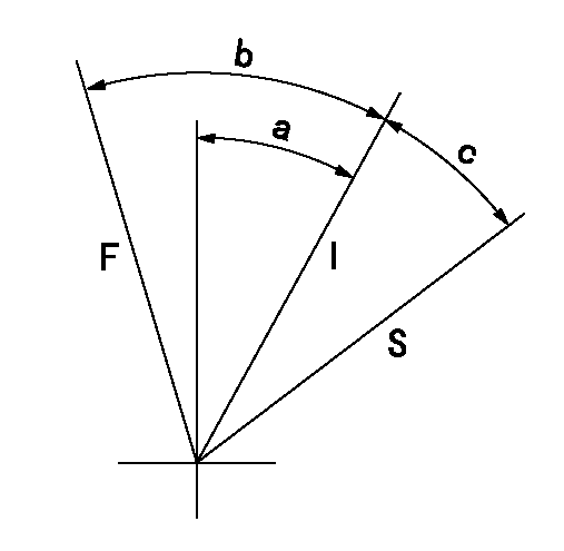
F:Full load
I:Idle
S:Stop
----------
----------
a=20.5deg+-3deg b=40deg+-5deg c=11deg+-5deg
----------
----------
a=20.5deg+-3deg b=40deg+-5deg c=11deg+-5deg
0000001501 MICRO SWITCH
Switch adjustment
Adjust the bolt so that the lower lever position is obtained when the switch is turned ON.
(1)Speed N1
(2)Rack position Ra
----------
N1=285+-10r/min Ra=7.1mm
----------
----------
N1=285+-10r/min Ra=7.1mm
----------
Information:
start by: a) remove flywheel housingb) remove timing gear coverc) remove pistons 1. Turn the crankshaft until the "C" mark on crankshaft gear (2) is in alignment with the "C" mark on camshaft gear (1). 2. Put a mark across the teeth of the fuel pump drive gear and idler gear at location (X). Put a mark across the teeth of the idler gear and camshaft gear at location (Y). The marks are necessary for the correct timing of the camshaft for the fuel injection pump when the crankshaft is installed.3. Fasten a hoist to the crankshaft.4. Remove the caps for the crankshaft main bearings.5. Remove the crankshaft. Weight of the crankshaft is 200 lb. (91 kg).6. Remove the main bearings from the main bearing caps. Remove the crankshaft main bearings from the cylinder block. 7. Use tool (A) to remove the crankshaft gear and the oil seal wear sleeve.Install Crankshaft
1. Clean the bearing surfaces in the cylinder block. Install the upper halves of the main bearings in the block. Put clean SAE 30 engine oil on the bearings.2. Heat the crankshaft gear to a maximum temperature of 601°F (316°C). Install the gear on the crankshaft. Fasten a hoist to the crankshaft and put the crankshaft in position in the cylinder block with all timing marks in alignment.3. Clean the bearing surfaces of the main bearing caps. Install the lower halves of the main bearings in the caps. 4. Install Plastigage (A) on the bearing to check the bearing clearance. See INSTALL CRANKSHAFT MAIN BEARINGS for the correct bearing clearance procedure. The main bearing caps must be installed with the part number toward the front of the block. Make sure the number on the cap is the same number as the number on the left side of each cap saddle. 5. Install thrust plate (1) (bearing) in the No. 7 main bearing. The thrust bearing has a tab that fits into a machined area in the cylinder block. The tab will not let the thrust bearing be installed backward.6. Put clean SAE 30 engine oil on the cap bolt threads, face of the washers and lower halves of the main bearings. Put the caps in position on the engine. Install the bolts and washers. Tighten the bolts to a torque of 30 3 lb.ft. (40 4 N m). Put a mark across the bolt heads and bearing, and tighten the bolts 90° clockwise from the mark. 7. Check the crankshaft end play with tool group (B). End play with new bearings must be .0025 to .0145 in. (0.064 to 0.368 mm). Maximum permissible end play with used bearings is .025 in. (0.64 mm). The crankshaft end play is controlled by the thrust plates (bearings).8. If the fuel pump drive gear, idler gear, or camshaft gear has been removed or if a replacement of the crankshaft gear has been made, it will be necessary to put the engine into time after assembly. See INSTALL FUEL INJECTION PUMP
1. Clean the bearing surfaces in the cylinder block. Install the upper halves of the main bearings in the block. Put clean SAE 30 engine oil on the bearings.2. Heat the crankshaft gear to a maximum temperature of 601°F (316°C). Install the gear on the crankshaft. Fasten a hoist to the crankshaft and put the crankshaft in position in the cylinder block with all timing marks in alignment.3. Clean the bearing surfaces of the main bearing caps. Install the lower halves of the main bearings in the caps. 4. Install Plastigage (A) on the bearing to check the bearing clearance. See INSTALL CRANKSHAFT MAIN BEARINGS for the correct bearing clearance procedure. The main bearing caps must be installed with the part number toward the front of the block. Make sure the number on the cap is the same number as the number on the left side of each cap saddle. 5. Install thrust plate (1) (bearing) in the No. 7 main bearing. The thrust bearing has a tab that fits into a machined area in the cylinder block. The tab will not let the thrust bearing be installed backward.6. Put clean SAE 30 engine oil on the cap bolt threads, face of the washers and lower halves of the main bearings. Put the caps in position on the engine. Install the bolts and washers. Tighten the bolts to a torque of 30 3 lb.ft. (40 4 N m). Put a mark across the bolt heads and bearing, and tighten the bolts 90° clockwise from the mark. 7. Check the crankshaft end play with tool group (B). End play with new bearings must be .0025 to .0145 in. (0.064 to 0.368 mm). Maximum permissible end play with used bearings is .025 in. (0.64 mm). The crankshaft end play is controlled by the thrust plates (bearings).8. If the fuel pump drive gear, idler gear, or camshaft gear has been removed or if a replacement of the crankshaft gear has been made, it will be necessary to put the engine into time after assembly. See INSTALL FUEL INJECTION PUMP