Information injection-pump assembly
ZEXEL
101601-2280
1016012280
HINO
220001340B
220001340b

Rating:
Cross reference number
ZEXEL
101601-2280
1016012280
HINO
220001340B
220001340b
Zexel num
Bosch num
Firm num
Name
Calibration Data:
Adjustment conditions
Test oil
1404 Test oil ISO4113 or {SAEJ967d}
1404 Test oil ISO4113 or {SAEJ967d}
Test oil temperature
degC
40
40
45
Nozzle and nozzle holder
105780-8140
Bosch type code
EF8511/9A
Nozzle
105780-0000
Bosch type code
DN12SD12T
Nozzle holder
105780-2080
Bosch type code
EF8511/9
Opening pressure
MPa
17.2
Opening pressure
kgf/cm2
175
Injection pipe
Outer diameter - inner diameter - length (mm) mm 6-2-600
Outer diameter - inner diameter - length (mm) mm 6-2-600
Overflow valve
131424-4120
Overflow valve opening pressure
kPa
122.5
98
147
Overflow valve opening pressure
kgf/cm2
1.25
1
1.5
Tester oil delivery pressure
kPa
157
157
157
Tester oil delivery pressure
kgf/cm2
1.6
1.6
1.6
Direction of rotation (viewed from drive side)
Right R
Right R
Injection timing adjustment
Direction of rotation (viewed from drive side)
Right R
Right R
Injection order
1-4-2-6-
3-5
Pre-stroke
mm
1.9
1.85
1.95
Beginning of injection position
Drive side NO.1
Drive side NO.1
Difference between angles 1
Cal 1-4 deg. 60 59.5 60.5
Cal 1-4 deg. 60 59.5 60.5
Difference between angles 2
Cyl.1-2 deg. 120 119.5 120.5
Cyl.1-2 deg. 120 119.5 120.5
Difference between angles 3
Cal 1-6 deg. 180 179.5 180.5
Cal 1-6 deg. 180 179.5 180.5
Difference between angles 4
Cal 1-3 deg. 240 239.5 240.5
Cal 1-3 deg. 240 239.5 240.5
Difference between angles 5
Cal 1-5 deg. 300 299.5 300.5
Cal 1-5 deg. 300 299.5 300.5
Injection quantity adjustment
Adjusting point
A
Rack position
12.5
Pump speed
r/min
500
500
500
Average injection quantity
mm3/st.
122
119
125
Max. variation between cylinders
%
0
-4
4
Fixing the lever
*
Injection quantity adjustment_02
Adjusting point
B
Rack position
12.8
Pump speed
r/min
600
600
600
Average injection quantity
mm3/st.
125
123
127
Max. variation between cylinders
%
0
-4
4
Fixing the lever
*
Injection quantity adjustment_03
Adjusting point
C
Rack position
12.8
Pump speed
r/min
800
800
800
Average injection quantity
mm3/st.
129.7
127.7
131.7
Max. variation between cylinders
%
0
-2
2
Basic
*
Fixing the lever
*
Injection quantity adjustment_04
Adjusting point
D
Rack position
13.1
Pump speed
r/min
1125
1125
1125
Average injection quantity
mm3/st.
135.5
132.5
138.5
Max. variation between cylinders
%
0
-4
4
Fixing the lever
*
Injection quantity adjustment_05
Adjusting point
E
Rack position
8.5+-0.5
Pump speed
r/min
275
275
275
Average injection quantity
mm3/st.
46
41
51
Max. variation between cylinders
%
0
-13
13
Fixing the rack
*
Injection quantity adjustment_06
Adjusting point
F
Rack position
15.5++
Pump speed
r/min
50
50
50
Average injection quantity
mm3/st.
140
140
Fixing the rack
*
Remarks
Excess fuel for starting.
Excess fuel for starting.
Timer adjustment
Pump speed
r/min
450+-50
Advance angle
deg.
0
0
0
Remarks
Start
Start
Timer adjustment_02
Pump speed
r/min
600
Advance angle
deg.
1.3
0.8
1.8
Timer adjustment_03
Pump speed
r/min
800
Advance angle
deg.
3.3
2.8
3.8
Timer adjustment_04
Pump speed
r/min
1000
Advance angle
deg.
5.7
5.2
6.2
Timer adjustment_05
Pump speed
r/min
1150
Advance angle
deg.
8
7.5
8.5
Remarks
Finish
Finish
Test data Ex:
Governor adjustment
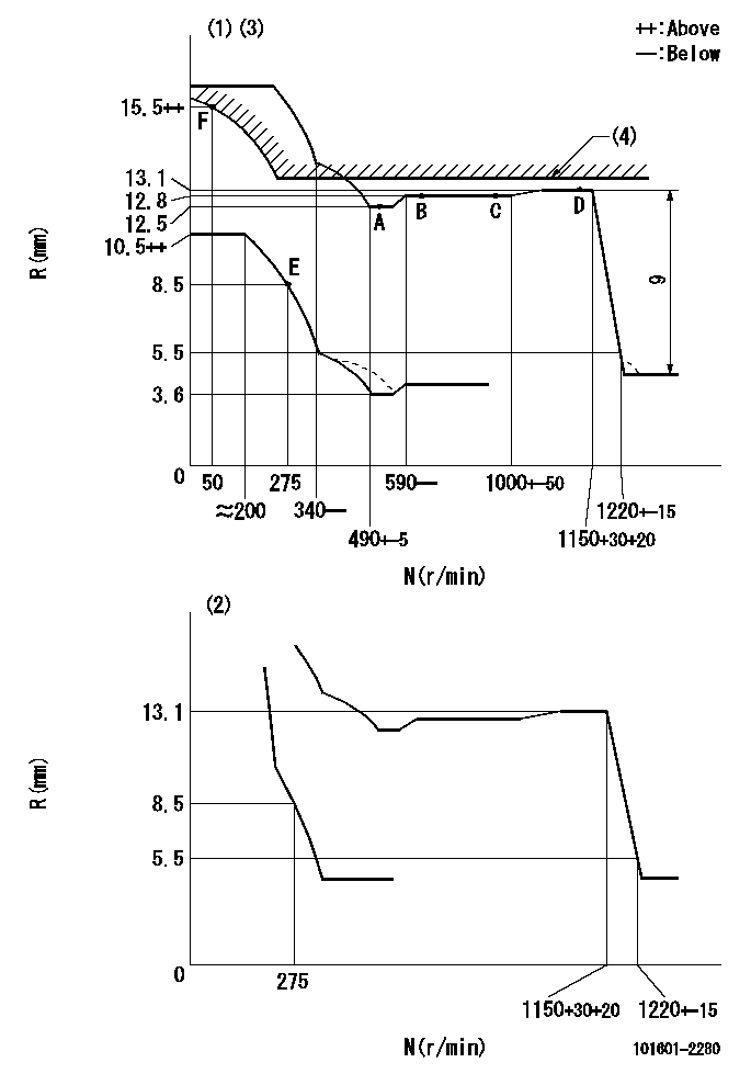
N:Pump speed
R:Rack position (mm)
(1)Adjust with speed control lever at full position (minimum-maximum speed specification)
(2)Adjust with the load control lever in the full position (variable speed specification).
(3)Beginning of damper spring operation: DL
(4)RACK LIMIT: RAL
----------
DL=5mm RAL=13.2+0.2mm
----------
----------
DL=5mm RAL=13.2+0.2mm
----------
Speed control lever angle
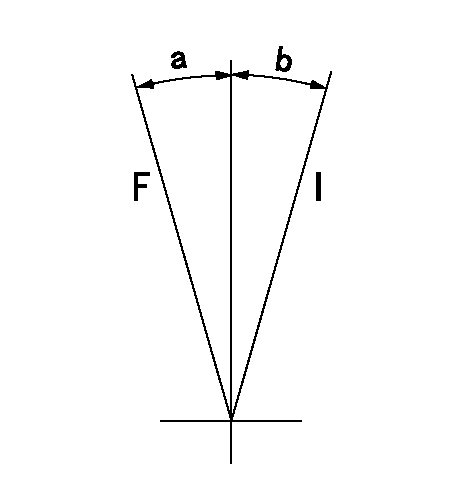
F:Full load
I:Idle
----------
----------
a=9.5deg+-3deg b=14deg+-3deg
----------
----------
a=9.5deg+-3deg b=14deg+-3deg
0000000901
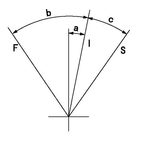
F:Full load
I:Idle
S:Stop
----------
----------
a=9.5deg+-3deg b=33deg+-5deg c=13deg+-5deg
----------
----------
a=9.5deg+-3deg b=33deg+-5deg c=13deg+-5deg
0000001501 MICRO SWITCH
Switch adjustment
Adjust the bolt so that the lower lever position is obtained when the switch is turned ON.
(1)Speed N1
(2)Rack position Ra
----------
N1=335+-10r/min Ra=8.5mm
----------
----------
N1=335+-10r/min Ra=8.5mm
----------
Information:
start by:a) remove pistons1. Check to be sure that all coolant has been removed from the cylinder block.2. Put a cover over the crankshaft journals before liners are removed. 3. Install tool (A) and remove the cylinder liners. 4. Remove filler band (1) and O-ring seals (2) from the cylinder liners.Install Cylinder Liners
1. Clean the cylinder liners and cylinder block. 2. Install the liners (1) in the cylinder block without the O-ring seals and filler bands. See CYLINDER LINER PROJECTION in TESTING AND ADJUSTING. 3. Install tooling (A) and two 5/8" - 11 NC bolts 5 1/2 in. long. Tighten the bolts evenly to 50 lb.ft. (70 N m).4. Check the liner projection with tool (B) at four locations around the liner.5. Liner projection must be .0020 to .0056 in. (0.051 to 0.142 mm). Measurements on the same liner must not be different by more than .002 in. (0.05 mm). Average measurement between liners next to each other must not be different by more than .002 in. (0.05 mm). The maximum permissible difference between average projection of all cylinder liners under one cylinder head is .004 in. (0.10 mm). The liner projection can change if the liner is turned in the bore. 6. If the liner projection is not .0020 to .0056 in. (0.051 to 0.142 mm), check the thickness of the liner flange (2) and the depth of the liner bore in the cylinder block. The thickness of the liner flange (2) must be .4048 .0008 in. (10.282 0.020 mm).7. The depth of the liner bore in the cylinder block must be .401 .001 in. (10.19 0.03 mm). If the liner bore in the block is worn and the measurement is not correct, the liner bore can be corrected with a cylinder block counterboring tool. See SPECIAL INSTRUCTIONS, FORM FM055228.8. Put a mark on the liner and cylinder block so the liner can be installed in the same position from which it was removed. 9. Install new O-ring seals (4) on the cylinder liners. Put liquid soap on the O-ring seals and in the bases in the cylinder block.
The liners must be installed in the cylinder block immediately after filler band (3) is installed. Make sure the marks on the liners and the cylinder block are in alignment when the cylinder liners are installed.
10. Put (dip) the filler band completely in clean SAE 30 oil and install it on the liner immediately.11. Install the liner in the cylinder block immediately with tooling (C).end by:a) install pistons