Information injection-pump assembly
ZEXEL
101601-2270
1016012270
HINO
220001260B
220001260b

Rating:
Cross reference number
ZEXEL
101601-2270
1016012270
HINO
220001260B
220001260b
Zexel num
Bosch num
Firm num
Name
Calibration Data:
Adjustment conditions
Test oil
1404 Test oil ISO4113 or {SAEJ967d}
1404 Test oil ISO4113 or {SAEJ967d}
Test oil temperature
degC
40
40
45
Nozzle and nozzle holder
105780-8140
Bosch type code
EF8511/9A
Nozzle
105780-0000
Bosch type code
DN12SD12T
Nozzle holder
105780-2080
Bosch type code
EF8511/9
Opening pressure
MPa
17.2
Opening pressure
kgf/cm2
175
Injection pipe
Outer diameter - inner diameter - length (mm) mm 6-2-600
Outer diameter - inner diameter - length (mm) mm 6-2-600
Overflow valve
131424-2220
Overflow valve opening pressure
kPa
123
103
143
Overflow valve opening pressure
kgf/cm2
1.25
1.05
1.45
Tester oil delivery pressure
kPa
157
157
157
Tester oil delivery pressure
kgf/cm2
1.6
1.6
1.6
Direction of rotation (viewed from drive side)
Right R
Right R
Injection timing adjustment
Direction of rotation (viewed from drive side)
Right R
Right R
Injection order
1-4-2-6-
3-5
Pre-stroke
mm
1.9
1.85
1.95
Beginning of injection position
Drive side NO.1
Drive side NO.1
Difference between angles 1
Cal 1-4 deg. 60 59.5 60.5
Cal 1-4 deg. 60 59.5 60.5
Difference between angles 2
Cyl.1-2 deg. 120 119.5 120.5
Cyl.1-2 deg. 120 119.5 120.5
Difference between angles 3
Cal 1-6 deg. 180 179.5 180.5
Cal 1-6 deg. 180 179.5 180.5
Difference between angles 4
Cal 1-3 deg. 240 239.5 240.5
Cal 1-3 deg. 240 239.5 240.5
Difference between angles 5
Cal 1-5 deg. 300 299.5 300.5
Cal 1-5 deg. 300 299.5 300.5
Injection quantity adjustment
Adjusting point
A
Rack position
12.5
Pump speed
r/min
500
500
500
Average injection quantity
mm3/st.
122
119
125
Max. variation between cylinders
%
0
-4
4
Fixing the lever
*
Injection quantity adjustment_02
Adjusting point
B
Rack position
12.8
Pump speed
r/min
600
600
600
Average injection quantity
mm3/st.
125
123
127
Max. variation between cylinders
%
0
-4
4
Fixing the lever
*
Injection quantity adjustment_03
Adjusting point
C
Rack position
12.8
Pump speed
r/min
800
800
800
Average injection quantity
mm3/st.
129.7
127.7
131.7
Max. variation between cylinders
%
0
-2
2
Basic
*
Fixing the lever
*
Injection quantity adjustment_04
Adjusting point
D
Rack position
13.1
Pump speed
r/min
1125
1125
1125
Average injection quantity
mm3/st.
135.5
132.5
138.5
Max. variation between cylinders
%
0
-4
4
Fixing the lever
*
Injection quantity adjustment_05
Adjusting point
E
Rack position
7.1+-0.5
Pump speed
r/min
225
225
225
Average injection quantity
mm3/st.
23
20
26
Max. variation between cylinders
%
0
-13
13
Fixing the rack
*
Injection quantity adjustment_06
Adjusting point
F
Rack position
15.5++
Pump speed
r/min
50
50
50
Average injection quantity
mm3/st.
140
140
Fixing the lever
*
Remarks
After startup boost setting
After startup boost setting
Timer adjustment
Pump speed
r/min
450+-50
Advance angle
deg.
0
0
0
Remarks
Start
Start
Timer adjustment_02
Pump speed
r/min
600
Advance angle
deg.
1.3
0.8
1.8
Timer adjustment_03
Pump speed
r/min
800
Advance angle
deg.
3.3
2.8
3.8
Timer adjustment_04
Pump speed
r/min
1000
Advance angle
deg.
5.7
5.2
6.2
Timer adjustment_05
Pump speed
r/min
1150
Advance angle
deg.
8
7.5
8.5
Remarks
Finish
Finish
Test data Ex:
Governor adjustment
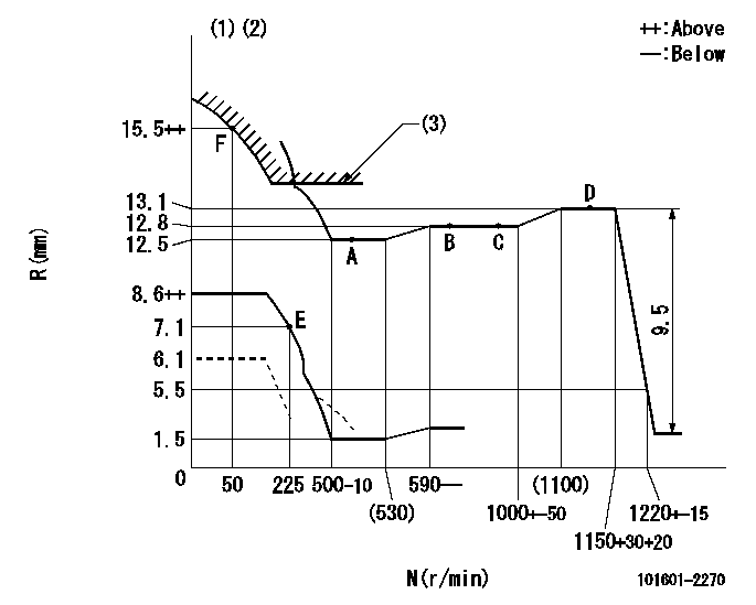
N:Pump speed
R:Rack position (mm)
(1)Set the load lever's stop position so that R = aa (N = 0).
(2)Beginning of damper spring operation: DL
(3)Excess fuel setting for starting: SXL
----------
aa=6.1mm DL=5-0.2mm SXL=13.2+0.2mm
----------
----------
aa=6.1mm DL=5-0.2mm SXL=13.2+0.2mm
----------
0000000901
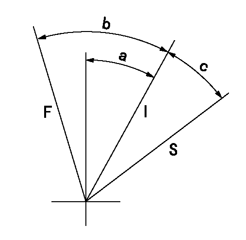
F:Full load
I:Idle
S:Stop
----------
----------
a=17deg+-3deg b=41deg+-3deg c=10deg+-2deg
----------
----------
a=17deg+-3deg b=41deg+-3deg c=10deg+-2deg
0000001501 MICRO SWITCH
Switch adjustment
Adjust the bolt so that the lower lever position is obtained when the switch is turned ON.
(1)Speed N1
(2)Rack position Ra
----------
N1=285+-10r/min Ra=7.1mm
----------
----------
N1=285+-10r/min Ra=7.1mm
----------
Information:
1. Remove two bolts (1) from the top of the water pump. Loosen two bolts (2) in the water pump.
TYPICAL EXAMPLE2. Remove oil supply line (3) from the turbocharger. Remove oil return line (4) from the turbocharger.
TYPICAL EXAMPLE3. Remove the bolts (5) that hold the cylinder head to the cylinder block.
TYPICAL EXAMPLE4. Fasten a hoist to the cylinder head assembly (6). Remove the cylinder head assembly from the block. Weight of the assembly is 290 lb. (131 kg). Remove O-ring seal from hollow dowel. Remove cylinder head gasket (7) and water ferrules.
Do not put the cylinder head down on a flat surface. This can cause damage to the fuel injection valves.
Always install a new gasket between spacer plate and cylinder block before cylinder head is installed. See REMOVE SPACER PLATE.Install Cylinder Head
TYPICAL EXAMPLE1. Thoroughly clean the spacer plate and bottom surface of the cylinder head. Install a new head gasket (2), water ferrules (1) and O-ring seal (3) on the hollow dowel. Be sure a new gasket has been installed between spacer plate and cylinder block. See INSTALL SPACER PLATE.2. Fasten a hoist and install the cylinder head assembly (4) on the cylinder block. 3. Install the push rods and put the rocker shaft in position on the cylinder head. Put 5P3931 Anti-Seize Compound on the threads of the cylinder head and rocker shaft bolts. Install the bolts and washers and tighten the bolts as follows: 1. Tighten all bolts in number sequence to a torque of 115 lb. ft. (155 N m).2. Again tighten all bolts in number sequence to a torque of 185 13 lb. ft. (250 17 N m).3. Again tighten all bolts in number sequence (hand torque only) to a torque of 185 13 lb. ft. (250 17 N m).4. Tighten all bolts in letter sequence to a torque of 32 5 lb. ft. (43 7 N m).4. Make adjustment of valves to have a clearance of .015 in. (0.38 mm) for intake and .025 in. (0.64 mm) for exhaust.
TYPICAL EXAMPLE5. Install oil return line (6) on the turbocharger.6. Install oil supply line (5) on the turbocharger. 7. Tighten the two bolts (8) in the water pump.8. Install the two bolts (7) that hold the water pump to the cylinder head.end by: a) install fuel injection lines