Information injection-pump assembly
ZEXEL
101601-2260
1016012260
HINO
220001150B
220001150b

Rating:
Cross reference number
ZEXEL
101601-2260
1016012260
HINO
220001150B
220001150b
Zexel num
Bosch num
Firm num
Name
Calibration Data:
Adjustment conditions
Test oil
1404 Test oil ISO4113 or {SAEJ967d}
1404 Test oil ISO4113 or {SAEJ967d}
Test oil temperature
degC
40
40
45
Nozzle and nozzle holder
105780-8140
Bosch type code
EF8511/9A
Nozzle
105780-0000
Bosch type code
DN12SD12T
Nozzle holder
105780-2080
Bosch type code
EF8511/9
Opening pressure
MPa
17.2
Opening pressure
kgf/cm2
175
Injection pipe
Outer diameter - inner diameter - length (mm) mm 6-2-600
Outer diameter - inner diameter - length (mm) mm 6-2-600
Overflow valve
131424-4120
Overflow valve opening pressure
kPa
122.5
98
147
Overflow valve opening pressure
kgf/cm2
1.25
1
1.5
Tester oil delivery pressure
kPa
157
157
157
Tester oil delivery pressure
kgf/cm2
1.6
1.6
1.6
Direction of rotation (viewed from drive side)
Right R
Right R
Injection timing adjustment
Direction of rotation (viewed from drive side)
Right R
Right R
Injection order
1-4-2-6-
3-5
Pre-stroke
mm
1.9
1.85
1.95
Beginning of injection position
Drive side NO.1
Drive side NO.1
Difference between angles 1
Cal 1-4 deg. 60 59.5 60.5
Cal 1-4 deg. 60 59.5 60.5
Difference between angles 2
Cyl.1-2 deg. 120 119.5 120.5
Cyl.1-2 deg. 120 119.5 120.5
Difference between angles 3
Cal 1-6 deg. 180 179.5 180.5
Cal 1-6 deg. 180 179.5 180.5
Difference between angles 4
Cal 1-3 deg. 240 239.5 240.5
Cal 1-3 deg. 240 239.5 240.5
Difference between angles 5
Cal 1-5 deg. 300 299.5 300.5
Cal 1-5 deg. 300 299.5 300.5
Injection quantity adjustment
Adjusting point
A
Rack position
12.5
Pump speed
r/min
500
500
500
Average injection quantity
mm3/st.
122
119
125
Max. variation between cylinders
%
0
-4
4
Fixing the lever
*
Injection quantity adjustment_02
Adjusting point
B
Rack position
12.8
Pump speed
r/min
800
800
800
Average injection quantity
mm3/st.
129.7
127.7
131.7
Max. variation between cylinders
%
0
-2
2
Basic
*
Fixing the lever
*
Injection quantity adjustment_03
Adjusting point
C
Rack position
12.8
Pump speed
r/min
1125
1125
1125
Average injection quantity
mm3/st.
131.3
128.3
134.3
Max. variation between cylinders
%
0
-4
4
Fixing the lever
*
Injection quantity adjustment_04
Adjusting point
D
Rack position
7.1+-0.5
Pump speed
r/min
225
225
225
Average injection quantity
mm3/st.
23
20
26
Max. variation between cylinders
%
0
-13
13
Fixing the lever
*
Injection quantity adjustment_05
Adjusting point
E
Rack position
15.5++
Pump speed
r/min
50
50
50
Average injection quantity
mm3/st.
140
140
Remarks
Excess fuel for starting.
Excess fuel for starting.
Timer adjustment
Pump speed
r/min
450+-50
Advance angle
deg.
0
0
0
Remarks
Start
Start
Timer adjustment_02
Pump speed
r/min
600
Advance angle
deg.
1.3
0.8
1.8
Timer adjustment_03
Pump speed
r/min
800
Advance angle
deg.
3.3
2.8
3.8
Timer adjustment_04
Pump speed
r/min
1000
Advance angle
deg.
5.7
5.2
6.2
Timer adjustment_05
Pump speed
r/min
1150
Advance angle
deg.
8
7.5
8.5
Remarks
Finish
Finish
Test data Ex:
Governor adjustment
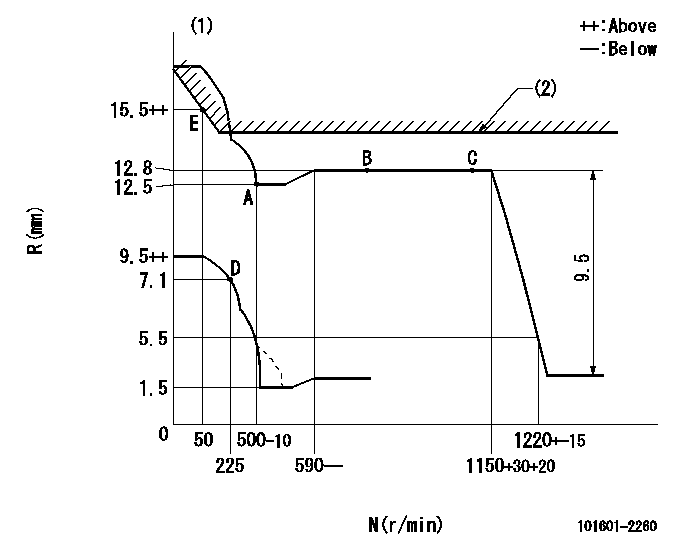
N:Pump speed
R:Rack position (mm)
(1)Beginning of damper spring operation: DL
(2)RACK LIMIT: RAL
----------
DL=5-0.2mm RAL=13+0.2mm
----------
----------
DL=5-0.2mm RAL=13+0.2mm
----------
0000000901
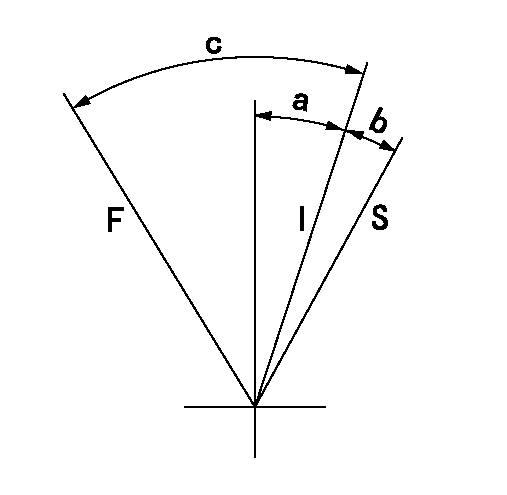
F:Full load
I:Idle
S:Stop
----------
----------
a=17deg+-3deg b=10deg+-2deg c=41deg+-3deg
----------
----------
a=17deg+-3deg b=10deg+-2deg c=41deg+-3deg
0000001501 MICRO SWITCH
Switch adjustment
Adjust the bolt so that the lower lever position is obtained when the switch is turned ON.
(1)Speed N1
(2)Rack position Ra
----------
N1=285+-10r/min Ra=7.1mm
----------
----------
N1=285+-10r/min Ra=7.1mm
----------
Information:
start by:a) remove turbocharger 1. Put the turbocharger in position on tool (A). Move tool (A) so the compressor housing is up. 2. For installation alignment purposes, make a mark on the center housing and turbine housing. Bend down the lock plates and remove six bolts (1). If some of the bolts are hard to remove, put penetrating oil on the bolt and hit the flat of the bolt head with a punch and hammer. 3. Lift the center housing and turbine wheel out of the turbine housing. If the assembly is hard to get apart, lift up on the compressor housing and hit the turbine housing with a soft hammer. 4. Remove clamp (2) from the compressor housing. For installation alignment purposes, make a mark on the center housing and the compressor housing. 5. Lift the center housing out of the compressor housing. Put the turbine wheel in tooling (B).6. Remove nut (3) with a universal socket. Remove O-ring (4).
Do not put a side force on the shaft when the nut is removed.
7. Heat the compressor wheel in oil for no more than ten minutes. The temperature of the oil must be 350° 25°F (176° 14°C).
The bearing heating oil used to heat the compressor wheel must have a flash point above 400°F (204°C).
8. Immediately after removing the compressor wheel from the oil, put the center housing in a press and use tooling (C) and (D) to remove the compressor wheel and center housing from the shaft.
Do not let the turbine wheel hit the bottom of the press.
9. Put the turbine wheel in tooling (B) and remove ring (6) and shroud (5). 10. Remove three bolts (7) and the three lock plates from center housing (8). 11. Remove plate (9) with tool (E). Remove the O-ring from plate (9). 12. Remove spacer (10) from plate (9). Remove collar (11) and thrust bearing (15). Remove bearing (12) and put a long dye mark on the top face of the bearing. Use tool (F) to remove rings (16) and (13). Remove bearing (17) and put a short dye mark on the top face of the bearing. Remove ring (14) with tool (F). The dye marks are for identification when installing the bearings.13. Inspect all parts and install new parts if needed. Use Special Instruction Form No. GMG00153-01, Turbocharger Reconditioning, Form No. FEG45138, Analyzing Turbocharger Failure and Video Tape JEG08054 (1/2 inch reel) (JEG09052-cassette), Turbocharger Reconditioning I (AIRESEARCH) for references.Assemble Turbocharger
1. Make sure all oil passages are open and clean. Put clean engine oil on all parts before assembly. 2. Install ring (3) with tool (A). Install bearing (4) with the short dye mark up. Install rings (2) and (1) with tool (A). Rings (1), (2) and (3) must be installed with the round edge toward the bearing. 3. Install shroud (5) on the turbine shaft. Install ring (6). Put 6V2055 High Vacuum Grease on ring (6) and fill the groove for the ring to one half depth all