Information injection-pump assembly
ZEXEL
101601-2220
1016012220
HINO
220001880A
220001880a

Rating:
Cross reference number
ZEXEL
101601-2220
1016012220
HINO
220001880A
220001880a
Zexel num
Bosch num
Firm num
Name
Calibration Data:
Adjustment conditions
Test oil
1404 Test oil ISO4113 or {SAEJ967d}
1404 Test oil ISO4113 or {SAEJ967d}
Test oil temperature
degC
40
40
45
Nozzle and nozzle holder
105780-8140
Bosch type code
EF8511/9A
Nozzle
105780-0000
Bosch type code
DN12SD12T
Nozzle holder
105780-2080
Bosch type code
EF8511/9
Opening pressure
MPa
17.2
Opening pressure
kgf/cm2
175
Injection pipe
Outer diameter - inner diameter - length (mm) mm 6-2-600
Outer diameter - inner diameter - length (mm) mm 6-2-600
Overflow valve
131424-4120
Overflow valve opening pressure
kPa
122.5
98
147
Overflow valve opening pressure
kgf/cm2
1.25
1
1.5
Tester oil delivery pressure
kPa
157
157
157
Tester oil delivery pressure
kgf/cm2
1.6
1.6
1.6
Direction of rotation (viewed from drive side)
Right R
Right R
Injection timing adjustment
Direction of rotation (viewed from drive side)
Right R
Right R
Injection order
1-4-2-6-
3-5
Pre-stroke
mm
1.9
1.85
1.95
Beginning of injection position
Drive side NO.1
Drive side NO.1
Difference between angles 1
Cal 1-4 deg. 60 59.5 60.5
Cal 1-4 deg. 60 59.5 60.5
Difference between angles 2
Cyl.1-2 deg. 120 119.5 120.5
Cyl.1-2 deg. 120 119.5 120.5
Difference between angles 3
Cal 1-6 deg. 180 179.5 180.5
Cal 1-6 deg. 180 179.5 180.5
Difference between angles 4
Cal 1-3 deg. 240 239.5 240.5
Cal 1-3 deg. 240 239.5 240.5
Difference between angles 5
Cal 1-5 deg. 300 299.5 300.5
Cal 1-5 deg. 300 299.5 300.5
Injection quantity adjustment
Adjusting point
A
Rack position
12.5
Pump speed
r/min
500
500
500
Average injection quantity
mm3/st.
122
119
125
Max. variation between cylinders
%
0
-4
4
Fixing the lever
*
Injection quantity adjustment_02
Adjusting point
B
Rack position
12.8
Pump speed
r/min
800
800
800
Average injection quantity
mm3/st.
129.7
127.7
131.7
Max. variation between cylinders
%
0
-2
2
Basic
*
Fixing the lever
*
Injection quantity adjustment_03
Adjusting point
C
Rack position
12.8
Pump speed
r/min
1125
1125
1125
Average injection quantity
mm3/st.
131.3
128.3
134.3
Max. variation between cylinders
%
0
-4
4
Fixing the lever
*
Injection quantity adjustment_04
Adjusting point
D
Rack position
7.1+-0.5
Pump speed
r/min
225
225
225
Average injection quantity
mm3/st.
46
43
49
Max. variation between cylinders
%
0
-13
13
Fixing the lever
*
Remarks
Excess fuel for starting.
Excess fuel for starting.
Injection quantity adjustment_05
Adjusting point
E
Rack position
15.5++
Pump speed
r/min
50
50
50
Average injection quantity
mm3/st.
140
140
Fixing the lever
*
Injection quantity adjustment_06
Adjusting point
F
Rack position
4.5
Pump speed
r/min
1000
1000
1000
Average injection quantity
mm3/st.
1
Timer adjustment
Pump speed
r/min
450+-50
Advance angle
deg.
0
0
0
Remarks
Start
Start
Timer adjustment_02
Pump speed
r/min
600
Advance angle
deg.
1.3
0.8
1.8
Timer adjustment_03
Pump speed
r/min
800
Advance angle
deg.
3.3
2.8
3.8
Timer adjustment_04
Pump speed
r/min
1000
Advance angle
deg.
5.7
5.2
6.2
Timer adjustment_05
Pump speed
r/min
1150
Advance angle
deg.
8
7.5
8.5
Remarks
Finish
Finish
Test data Ex:
Governor adjustment
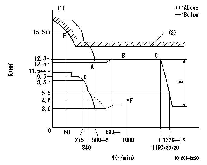
N:Pump speed
R:Rack position (mm)
(1)Beginning of damper spring operation: DL
(2)RACK LIMIT: RAL
----------
DL=5-0.2mm RAL=13+0.2mm
----------
----------
DL=5-0.2mm RAL=13+0.2mm
----------
0000000901
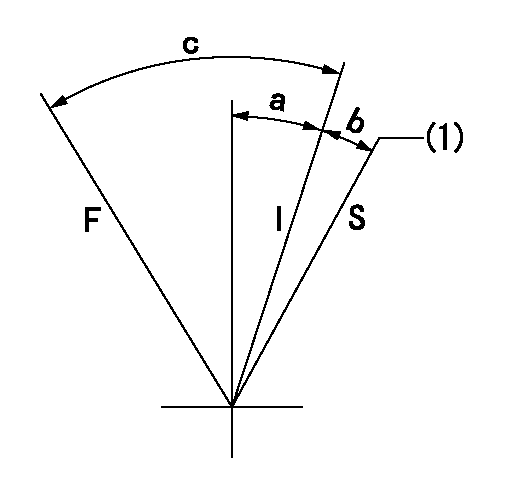
F:Full load
I:Idle
S:Stop
(1)Pump speed aa, rack position bb
----------
aa=150r/min bb=6.5mm
----------
a=22deg-5deg b=13deg+-3deg c=33deg+-3deg
----------
aa=150r/min bb=6.5mm
----------
a=22deg-5deg b=13deg+-3deg c=33deg+-3deg
0000001501 MICRO SWITCH
Switch adjustment
Adjust the bolt so that the lower lever position is obtained when the switch is turned ON.
(1)Speed N1
(2)Rack position Ra
----------
N1=335r/min Ra=8.5mm
----------
----------
N1=335r/min Ra=8.5mm
----------
Information:
start by:a) remove oil pump1. Turn the crankshaft until two pistons are at bottom center. Remove the connecting rod caps from the two connecting rods. Remove the lower half of the bearings from the caps.2. Push the connecting rods away from the crankshaft and remove the upper half of the bearings.3. Clean the bearing contact surfaces in the caps and rods. Install the upper halves of the bearings in the connecting rods. Put clean SAE 30 engine oil on the bearings and crankshaft journals. Put the connecting rods in position on the crankshaft.4. Install the lower halves of the new bearings in the caps. Put clean SAE 30 engine oil on the bearings and on the threads of all bolts. 5. Put Plastigage (A) on the bearing to check the bearing clearance. Put the caps in position on the connecting rods and install the nuts on the bolts. Tighten the nuts to a torque of 30 3 lb.ft. (40 4 N m). Put a mark across the nuts and bolts, and turn the nuts 90° more from the marks as shown. 6. Remove the rod cap and measure the thickness of the Plastigage to find the bearing clearance. Clearance with new bearings must be .0030 to .0066 in. (0.076 to 0.168 mm). Maximum permissible clearance with used bearings is .010 in. (0.25 mm).7. Put clean oil on the lower halves of the bearings and on the threads of the bolts. Put the caps in position on the connecting rods and install the nuts on the bolts. Tighten both nuts to a torque of 30 3 lb.ft. (40 4 N m). Put a mark across the nuts and bolts, and turn the nuts 90° more from the mark as shown.
Make sure the number on the side of the connecting rod is the same number and on the same side as the number on the cap.
8. Do the above steps again for the remainder of the connecting rod bearings.end by:a) install oil pump
Make sure the number on the side of the connecting rod is the same number and on the same side as the number on the cap.
8. Do the above steps again for the remainder of the connecting rod bearings.end by:a) install oil pump