Information injection-pump assembly
BOSCH
F 019 Z10 973
f019z10973
ZEXEL
101502-9150
1015029150
KUBOTA
1G41851011
1g41851011
Rating:
Service parts 101502-9150 INJECTION-PUMP ASSEMBLY:
1.
_
6.
COUPLING PLATE
7.
COUPLING PLATE
8.
_
9.
_
11.
Nozzle and Holder
12.
Open Pre:MPa(Kqf/cm2)
18.6(190)/22.6(230)
14.
NOZZLE
Cross reference number
BOSCH
F 019 Z10 973
f019z10973
ZEXEL
101502-9150
1015029150
KUBOTA
1G41851011
1g41851011
Zexel num
Bosch num
Firm num
Name
101502-9150
F 019 Z10 973
1G41851011 KUBOTA
INJECTION-PUMP ASSEMBLY
F5802- K 14BZ INJECTION PUMP ASSY PE
F5802- K 14BZ INJECTION PUMP ASSY PE
Calibration Data:
Adjustment conditions
Test oil
1404 Test oil ISO4113 or {SAEJ967d}
1404 Test oil ISO4113 or {SAEJ967d}
Test oil temperature
degC
40
40
45
Nozzle and nozzle holder
105780-8140
Bosch type code
EF8511/9A
Nozzle
105780-0000
Bosch type code
DN12SD12T
Nozzle holder
105780-2080
Bosch type code
EF8511/9
Opening pressure
MPa
17.2
Opening pressure
kgf/cm2
175
Injection pipe
Outer diameter - inner diameter - length (mm) mm 6-2-600
Outer diameter - inner diameter - length (mm) mm 6-2-600
Overflow valve
134424-4120
Overflow valve opening pressure
kPa
255
221
289
Overflow valve opening pressure
kgf/cm2
2.6
2.25
2.95
Tester oil delivery pressure
kPa
255
255
255
Tester oil delivery pressure
kgf/cm2
2.6
2.6
2.6
Direction of rotation (viewed from drive side)
Left L
Left L
Injection timing adjustment
Direction of rotation (viewed from drive side)
Left L
Left L
Injection order
1-3-5-4-
2
Pre-stroke
mm
4
3.95
4.05
Beginning of injection position
Drive side NO.1
Drive side NO.1
Difference between angles 1
Cal 1-3 deg. 72 71.5 72.5
Cal 1-3 deg. 72 71.5 72.5
Difference between angles 2
Cal 1-5 deg. 144 143.5 144.5
Cal 1-5 deg. 144 143.5 144.5
Difference between angles 3
Cal 1-4 deg. 216 215.5 216.5
Cal 1-4 deg. 216 215.5 216.5
Difference between angles 4
Cyl.1-2 deg. 288 287.5 288.5
Cyl.1-2 deg. 288 287.5 288.5
Injection quantity adjustment
Adjusting point
A
Rack position
13.2
Pump speed
r/min
1200
1200
1200
Average injection quantity
mm3/st.
102
101
103
Max. variation between cylinders
%
0
-2.5
2.5
Basic
*
Fixing the lever
*
Injection quantity adjustment_02
Adjusting point
B
Rack position
12.55
Pump speed
r/min
650
650
650
Average injection quantity
mm3/st.
107.5
97.5
117.5
Fixing the lever
*
Injection quantity adjustment_03
Adjusting point
C
Rack position
7.7+-0.5
Pump speed
r/min
350
350
350
Average injection quantity
mm3/st.
13
11
15
Max. variation between cylinders
%
0
-15
15
Fixing the rack
*
Injection quantity adjustment_04
Adjusting point
E
Rack position
13.4++
Pump speed
r/min
100
100
100
Average injection quantity
mm3/st.
115
115
125
Fixing the lever
*
Rack limit
*
Timer adjustment
Pump speed
r/min
(800)
Advance angle
deg.
0.5
Timer adjustment_02
Pump speed
r/min
(1100)
Advance angle
deg.
2
1.7
2.3
Remarks
Finish
Finish
Test data Ex:
Governor adjustment
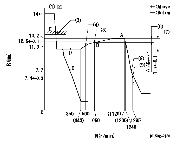
N:Pump speed
R:Rack position (mm)
(1)Target notch: K
(2)Tolerance for racks not indicated: +-0.05mm.
(3)RACK LIMIT
(4)Set the idle spring.
(5)The torque control spring must does not have a set force.
(6)Rack difference between N = N1 and N = N2
(7)Rack difference between N = N3 and N = N4
(8)Idle sub spring setting: L1.
(9)Main spring setting
----------
K=10 N1=1200r/min N2=650r/min N3=1200r/min N4=350r/min L1=8.3-0.5mm
----------
----------
K=10 N1=1200r/min N2=650r/min N3=1200r/min N4=350r/min L1=8.3-0.5mm
----------
Speed control lever angle
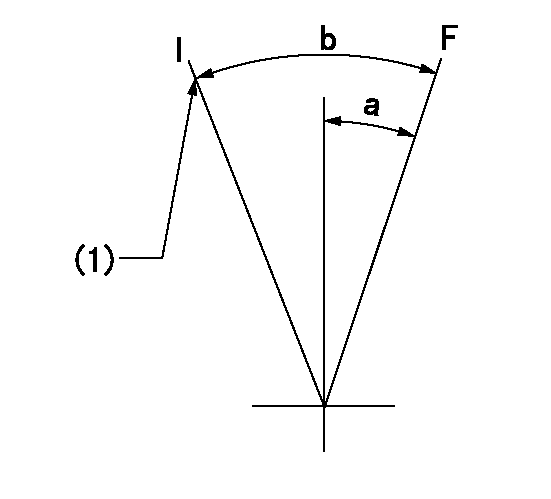
F:Full speed
I:Idle
(1)Stopper bolt setting
----------
----------
a=15deg+-5deg b=37deg+-5deg
----------
----------
a=15deg+-5deg b=37deg+-5deg
Stop lever angle
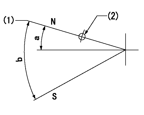
N:Pump normal
S:Stop the pump.
(1)Normal
(2)Use the hole at R = aa
----------
aa=60mm
----------
a=19deg+-5deg b=53deg+-5deg
----------
aa=60mm
----------
a=19deg+-5deg b=53deg+-5deg
Timing setting
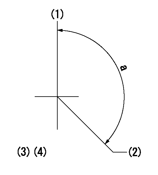
(1)Pump vertical direction
(2)Position of camshaft's key groove at No 1 cylinder's beginning of injection
(3)-
(4)-
----------
----------
a=(130deg)
----------
----------
a=(130deg)
Information:
(1) Torque for bushing ... 150 10 lb. ft.(20.7 1.4 mkg)(2) Thickness of spacers: 5M2697 Spacer ... .170 in.(4.32 mm)2M4208 Spacer ... .174 in.(4.42 mm)2M4209 Spacer ... .178 in.(4.52 mm)2M4210 Spacer ... .182 in.(4.62 mm)2M4211 Spacer ... .186 in.(4.72 mm)2M4212 Spacer ... .190 in.(4.82 mm)5M2691 Spacer ... .194 in.(4.93 mm)5S7189 Spacer ... .198 in.(5.03 mm)(3) 1S7590 Spring: Length under test force ... 1.522 in.(38.66 mm)Test force ... 22.6 1.1 lbs.(10.25 5 kg)Free length after test ... 1.751 in.(44.47 mm)Outside diameter ... .995 in.(25.27 mm)(4) Timing dimension for the fuel injection pumps: On engine with 8S7167 Gauge (A) ... 4.355 .002 in.(110.62 0.05 mm)Off engine with 8S7167 Gauge (A) ... 4.392 .002 in.(11.56 0.05 mm)(5) Length of pump plunger ... 2.7212 .0015 in.(69.118 0.038 mm) Minimum permissible length ... 2.7147 in.(68.953 mm)(6) Bore in the bearings for the rack: Bearing at the rear (later) ... .5020 .0015 in.(12.751 0.038 mm)Bearing at the front (later) ... .5023 .0015 in.(12.758 0.038 mm)Both bearings (earlier) ... .5010 .0003 in.(12.725 0.008 mm)Diameter of fuel rack ... .4983 to .4987 in.(12.656 to 12.666 mm)Maximum permissible clearance between rack and bearings ... .005 in.(0.13 mm)(7) Bore in bearings for the camshaft ... 2.1245 to 2.1255 in.(53.962 to 53.987 mm) Diameter of bearing journals of the camshaft ... 2.1215 to 2.1225 in.(53.886 to 53.911 mm)Maximum permissible clearance between the bearings and the camshaft journals ... .010 in.(0.25 mm) (8) Torque for the nuts that hold the fuel lines ... 30 5 lb. ft.(4.1 0.7 mkg)(9) Torque for the nuts that hold the nozzles ... 55 5 lb. ft.(7.6 0.7 mkg)(10) Body(11) Tighten nozzle finger tight in body.(12) Torque for glow plug ... 120 24 lb. in.(138.4 27.6 cm.kg)(13) Torque for precombustion chamber ... 150 10 lb. ft.(20.7 1.4 mkg)
Have questions with 101502-9150?
Group cross 101502-9150 ZEXEL
Kubota
101502-9150
F 019 Z10 973
1G41851011
INJECTION-PUMP ASSEMBLY
F5802-
F5802-