Information injection-pump assembly
ZEXEL
101501-2060
1015012060
HINO
220009740A
220009740a

Rating:
Cross reference number
ZEXEL
101501-2060
1015012060
HINO
220009740A
220009740a
Zexel num
Bosch num
Firm num
Name
Calibration Data:
Adjustment conditions
Test oil
1404 Test oil ISO4113 or {SAEJ967d}
1404 Test oil ISO4113 or {SAEJ967d}
Test oil temperature
degC
40
40
45
Nozzle and nozzle holder
105780-8250
Bosch type code
1 688 901 101
Nozzle
105780-0120
Bosch type code
1 688 901 990
Nozzle holder
105780-2190
Opening pressure
MPa
20.7
Opening pressure
kgf/cm2
211
Injection pipe
Outer diameter - inner diameter - length (mm) mm 6-2-600
Outer diameter - inner diameter - length (mm) mm 6-2-600
Overflow valve
131425-0320
Overflow valve opening pressure
kPa
108
88
128
Overflow valve opening pressure
kgf/cm2
1.1
0.9
1.3
Tester oil delivery pressure
kPa
255
255
255
Tester oil delivery pressure
kgf/cm2
2.6
2.6
2.6
Direction of rotation (viewed from drive side)
Left L
Left L
Injection timing adjustment
Direction of rotation (viewed from drive side)
Left L
Left L
Injection order
1-2-4-5-
3
Pre-stroke
mm
4
3.97
4.03
Beginning of injection position
Governor side NO.1
Governor side NO.1
Difference between angles 1
Cyl.1-2 deg. 72 71.75 72.25
Cyl.1-2 deg. 72 71.75 72.25
Difference between angles 2
Cal 1-4 deg. 144 143.75 144.25
Cal 1-4 deg. 144 143.75 144.25
Difference between angles 3
Cal 1-5 deg. 216 215.75 216.25
Cal 1-5 deg. 216 215.75 216.25
Difference between angles 4
Cal 1-3 deg. 288 287.75 288.25
Cal 1-3 deg. 288 287.75 288.25
Injection quantity adjustment
Adjusting point
-
Rack position
12.2
Pump speed
r/min
850
850
850
Average injection quantity
mm3/st.
100
98.4
101.6
Max. variation between cylinders
%
0
-3.5
3.5
Basic
*
Fixing the rack
*
Standard for adjustment of the maximum variation between cylinders
*
Injection quantity adjustment_02
Adjusting point
Z
Rack position
9.5+-0.5
Pump speed
r/min
415
415
415
Each cylinder's injection qty
mm3/st.
12
11
13
Fixing the rack
*
Standard for adjustment of the maximum variation between cylinders
*
Injection quantity adjustment_03
Adjusting point
A
Rack position
R1(12.2)
Pump speed
r/min
850
850
850
Average injection quantity
mm3/st.
100
99
101
Basic
*
Fixing the lever
*
Injection quantity adjustment_04
Adjusting point
B
Rack position
R1+0.6
Pump speed
r/min
1450
1450
1450
Average injection quantity
mm3/st.
103
99
107
Fixing the lever
*
Injection quantity adjustment_05
Adjusting point
C
Rack position
R1+0.45
Pump speed
r/min
1160
1160
1160
Average injection quantity
mm3/st.
105.5
101.5
109.5
Fixing the lever
*
Injection quantity adjustment_06
Adjusting point
D
Rack position
R1-0.75
Pump speed
r/min
580
580
580
Average injection quantity
mm3/st.
84
80
88
Fixing the lever
*
Injection quantity adjustment_07
Adjusting point
E
Rack position
R1-0.9
Pump speed
r/min
300
300
300
Average injection quantity
mm3/st.
77
71
83
Fixing the lever
*
Injection quantity adjustment_08
Adjusting point
I
Rack position
-
Pump speed
r/min
100
100
100
Average injection quantity
mm3/st.
170
170
180
Fixing the lever
*
Rack limit
*
Timer adjustment
Pump speed
r/min
950--
Advance angle
deg.
0
0
0
Load
1/5
Remarks
Start
Start
Timer adjustment_02
Pump speed
r/min
900
Advance angle
deg.
0.3
Load
1/5
Timer adjustment_03
Pump speed
r/min
-
Advance angle
deg.
1
0.7
1.3
Load
5/5
Remarks
Measure the actual speed.
Measure the actual speed.
Timer adjustment_04
Pump speed
r/min
1190++
Advance angle
deg.
1
0.7
1.3
Load
2/5
Timer adjustment_05
Pump speed
r/min
(1300-50
)
Advance angle
deg.
1
0.7
1.3
Load
5/5
Remarks
Measure the actual speed.
Measure the actual speed.
Timer adjustment_06
Pump speed
r/min
1450-50
Advance angle
deg.
5.5
5.2
5.8
Load
5/5
Remarks
Finish
Finish
Test data Ex:
Governor adjustment
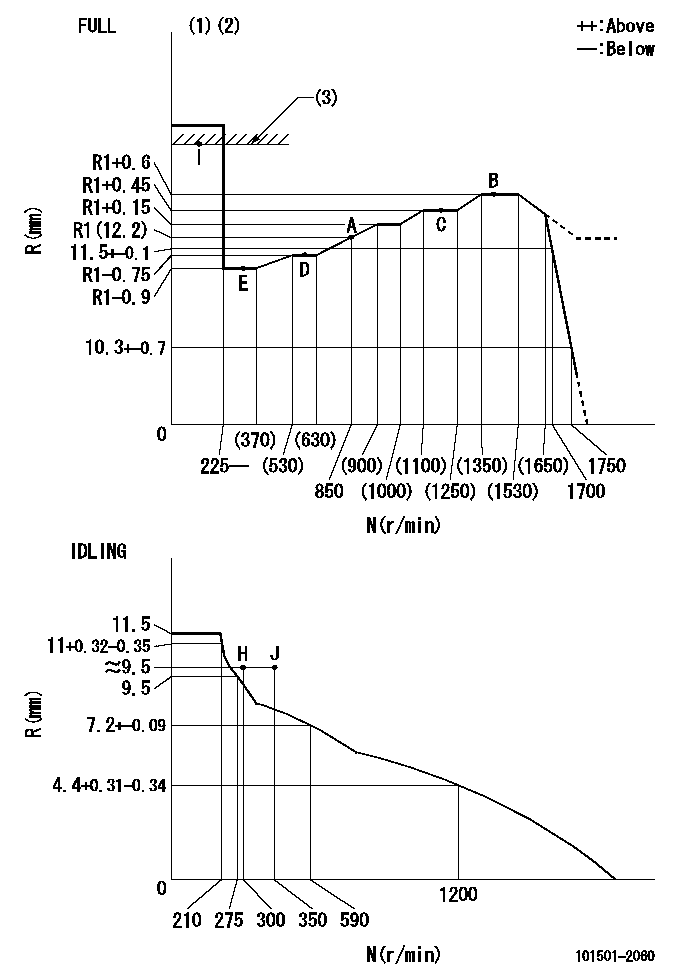
N:Pump speed
R:Rack position (mm)
(1)Torque cam stamping: T1
(2)Tolerance for racks not indicated: +-0.05mm.
(3)RACK LIMIT
----------
T1=K64
----------
----------
T1=K64
----------
Speed control lever angle

F:Full speed
I:Idle
(1)Use the hole at R = aa
(2)Stopper bolt set position 'H'
----------
aa=46mm
----------
a=8deg+-5deg b=38deg+-3deg
----------
aa=46mm
----------
a=8deg+-5deg b=38deg+-3deg
Stop lever angle
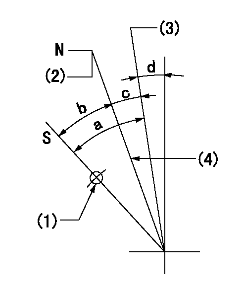
N:Engine manufacturer's normal use
S:Stop the pump.
(1)Use the hole at R = aa
(2)Rack position bb
(3)Free
(4)Set the stopper screw. (After setting, apply red paint.)
----------
aa=50mm bb=16.2+-0.2mm
----------
a=(36deg) b=26deg+-5deg c=10deg+-5deg d=0deg+-5deg
----------
aa=50mm bb=16.2+-0.2mm
----------
a=(36deg) b=26deg+-5deg c=10deg+-5deg d=0deg+-5deg
Timing setting

(1)Pump vertical direction
(2)Coupling's key groove position at No 1 cylinder's beginning of injection
(3)-
(4)-
----------
----------
a=(20deg)
----------
----------
a=(20deg)
Information:
Image1.1.2
2. Remove existing 215-2705 cap (Image 1.2.1), and replace with new 272-7102 cap, utilizing the existing cap screws (Image 1.2.1). Insure that threads are coated with Thread Lock P/N 9S-3263 or 4C-4030 and torque cap screws to 7(+/-1) Nm.
Image1.2.1
3. Install new 263-2905 switches (Image 1.3.1) into caps insuring that threads are coated with P/N 4C-5598 High temperature Anti-Seize and torque to 16(+/-2) Nm
Image1.3.1
4. Connect new switch to the applicable wiring harness. Install ladder clips as shown (Image 1.4.1), using 0S-1588 Bolts coated with P/N 4C-5598 High Temperature Anti-Seize to replace the top two existing bolts as shown. Torque these bolts to 47 (+/-9) Nm.
Image1.4.1
Image1.4.2
5. IMPORTANT - Tie-wrap new switch wiring to existing solenoid wiring as shown (Images 1.4.1 & 1.4.2), to prevent thermal damage to wiring.
6. Install information films P/N 179-0133 on electrically actuated Air Shut Offs over the existing films on the solenoids as shown in (Image 1.6.1) or install information films for hydraulically actuated Air Shut Offs over the existing films on the valve covers as shown in (Image 1.6.2).
Films in languages other than English are available under the following part numbers:
-Arabic 297-2613
-French 297-2614
-German 297-2615
-Spanish 297-2616
-Portuguese 297-2617
-Russian 297-2618
Image1.6.1
Image1.6.2
Important Notes:
1. If a new switch is to be painted, mask the vent holes around the perimeter of the switch before painting and be sure to remove the masking after the paint dries.
2. Test completed modifications as detailed below for the specific ECM installed on the engine (ADEM 2 or ADEM 3).
OPERATIONAL TEST - ADEM 2 Engine Control Modules ONLY
Note: (For Troubleshooting purposes) The ASO switches are normally closed switches that are in the closed state when the air shutoff valves are latched in the open ("Run") position. If the air shutoff valves are in the closed ("Stop") position, the switch will be in the open state, causing an emergency stop and shutting the engine down. This also prevents the engine from starting.
DO NOT START THE ENGINE! Ensure that the engine control is in the "OFF" position.
1. Ensure that both air shutoff gates are latched in the OPEN position and ensure that both air shutoff switches are connected. Turn on the power to the engine control panel. Both air shutoff gates should remain open. If both air shutoff gates do not remain open, check the wiring for the air shutoff switches.
2. With the power for the engine control panel in the ON position, activate the "EMERGENCY STOP" switch. Both of the air shutoff gates should close. If both air shutoff gates close, proceed to step 3. If both air shutoff gates do not close, check the wiring for the air shutoff switches and check the wiring for the solenoids. Activate the "EMERGENCY STOP" switch again. When both air shutoff gates close, proceed to step 3.
3. Turn the power to the engine control panel to the OFF position. Ensure that the "EMERGENCY STOP" switch is in the RUN position. Latch only the right side air shutoff gate to the OPEN position. Turn the power for the engine control panel to