Information injection-pump assembly
ZEXEL
101495-3600
1014953600
Rating:
Cross reference number
ZEXEL
101495-3600
1014953600
Zexel num
Bosch num
Firm num
Name
101495-3600
INJECTION-PUMP ASSEMBLY
S4D95LE-3
S4D95LE-3
Calibration Data:
Adjustment conditions
Test oil
1404 Test oil ISO4113 or {SAEJ967d}
1404 Test oil ISO4113 or {SAEJ967d}
Test oil temperature
degC
40
40
45
Nozzle and nozzle holder
105780-8140
Bosch type code
EF8511/9A
Nozzle
105780-0000
Bosch type code
DN12SD12T
Nozzle holder
105780-2080
Bosch type code
EF8511/9
Opening pressure
MPa
17.2
Opening pressure
kgf/cm2
175
Injection pipe
Outer diameter - inner diameter - length (mm) mm 6-2-600
Outer diameter - inner diameter - length (mm) mm 6-2-600
Tester oil delivery pressure
kPa
157
157
157
Tester oil delivery pressure
kgf/cm2
1.6
1.6
1.6
Direction of rotation (viewed from drive side)
Right R
Right R
Injection timing adjustment
Direction of rotation (viewed from drive side)
Right R
Right R
Injection order
1-2-4-3
Pre-stroke
mm
3.2
3.15
3.25
Rack position
After adjusting injection quantity. R=A
After adjusting injection quantity. R=A
Beginning of injection position
Drive side NO.1
Drive side NO.1
Difference between angles 1
Cyl.1-2 deg. 90 89.5 90.5
Cyl.1-2 deg. 90 89.5 90.5
Difference between angles 2
Cal 1-4 deg. 180 179.5 180.5
Cal 1-4 deg. 180 179.5 180.5
Difference between angles 3
Cal 1-3 deg. 270 269.5 270.5
Cal 1-3 deg. 270 269.5 270.5
Injection quantity adjustment
Adjusting point
A
Rack position
10.3
Pump speed
r/min
900
900
900
Average injection quantity
mm3/st.
90
89
91
Max. variation between cylinders
%
0
-2.5
2.5
Basic
*
Fixing the lever
*
Injection quantity adjustment_02
Adjusting point
-
Rack position
7.8+-0.5
Pump speed
r/min
400
400
400
Average injection quantity
mm3/st.
13.5
12.5
14.5
Max. variation between cylinders
%
0
-15
15
Fixing the rack
*
Remarks
Adjust only variation between cylinders; adjust governor according to governor specifications.
Adjust only variation between cylinders; adjust governor according to governor specifications.
Test data Ex:
Governor adjustment
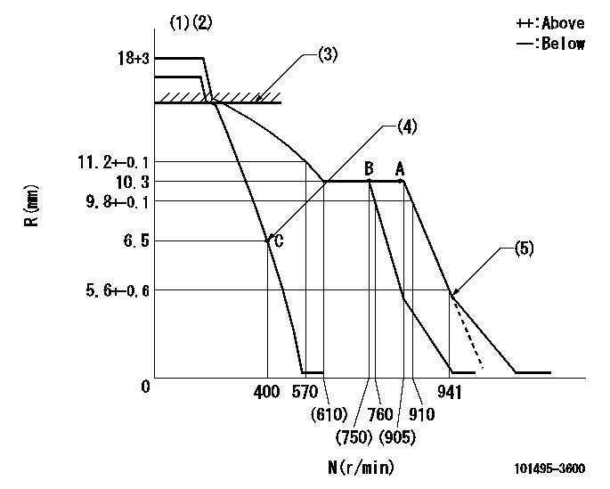
N:Pump speed
R:Rack position (mm)
(1)Target notch: K
(2)Tolerance for racks not indicated: +-0.05mm.
(3)RACK CAP: R1
(4)Main spring setting
(5)Idle sub spring setting: L1.
----------
K=12 R1=(17.5)mm L1=5.5-0.2mm
----------
----------
K=12 R1=(17.5)mm L1=5.5-0.2mm
----------
Speed control lever angle
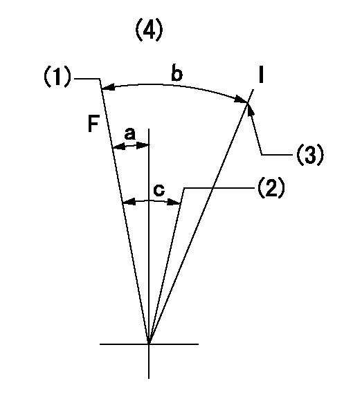
F:Full speed
I:Idle
(1)Set the pump speed at aa. ( At delivery )
(2)When pump speed set at bb
(3)Stopper bolt setting
(4)Use the hole above R = cc
----------
aa=910r/min bb=760r/min cc=60mm
----------
a=7deg+-5deg b=25deg+-5deg c=7deg+-5deg
----------
aa=910r/min bb=760r/min cc=60mm
----------
a=7deg+-5deg b=25deg+-5deg c=7deg+-5deg
Stop lever angle
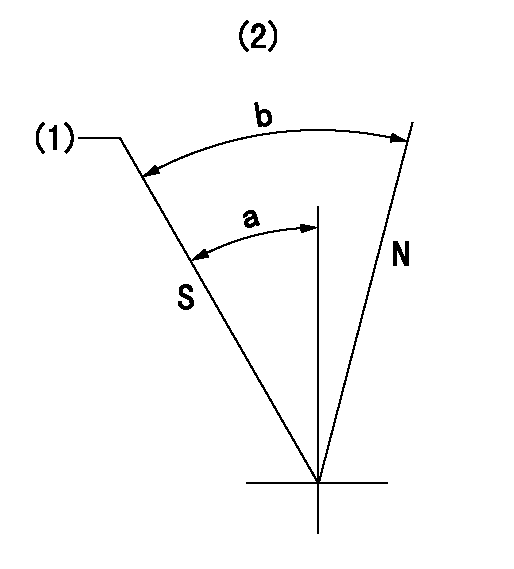
N:Pump normal
S:Stop the pump.
(1)Rack position = aa, speed = bb (stamp at delivery)
(2)No return spring
----------
aa=3-0.5mm bb=0r/min
----------
a=22.5deg+-5deg b=(50deg)
----------
aa=3-0.5mm bb=0r/min
----------
a=22.5deg+-5deg b=(50deg)
0000001501 I/P WITH LOAD PLUNGER ADJ
Load plunger-equipped pump adjustment
1. Adjust the variation between cylinders and the injection quantity.
2. At Full point A, adjust the pre-stroke to the specified value.
3. After pre-stroke adjustment, reconfirm that the fuel injection quantity and the variation between cylinders is as specified.
----------
----------
----------
----------
Timing setting

(1)Pump vertical direction
(2)Position of key groove at No 1 cylinder's beginning of injection
(3)Stamp aligning marks on the pump housing flange.
(4)After adjusting the injection quantity, adjust at rack position aa.
(5)-
----------
aa=10.3mm
----------
a=58deg+-3deg b=2deg+-30min
----------
aa=10.3mm
----------
a=58deg+-3deg b=2deg+-30min
Information:
The electrical system is a combination of two separate electric circuits: The charging circuit and the starting circuit. Each circuit is dependent on some of the same components. The battery (batteries), on-off start switch, circuit breaker, ammeter, cables and wires from the battery are common in each of the circuits.
The ignition switch must be ON to allow the electrical system to function. Some charging circuit components will be damaged if the engine is operated with the ignition switch OFF.
The charging circuit is in operation when the diesel engine is operating. The electricity producing (charging) unit is an alternator. A regulator in the circuit senses the state of charge in the battery and regulates the alternator output to keep the batter fully charged.The alternator has four main components: end frame assembly (brush end), rotor assembly, stator and shell assembly, and end frame assembly (drive end).A separate regulator senses the charge condition of the battery as well as electrical system power demand and controls the alternator output accordingly by limiting the field current.
ALTERNATOR
Never operate the alternator without the battery in the circuit. Making or breaking an alternator connection with a heavy load on the circuit will sometimes result in regulator damage.
The starting motor is a device used to rotate the flywheel of an engine fast enough to start the engine.
ALTERNATOR REGULATOR
ELECTRIC STARTING MOTORThe starting motor includes a solenoid. The solenoid engages the pinion with the ring gear on the engine flywheel, when the solenoid is energized. The pinion always engages before the electric contacts in the solenoid causes the circuit between the battery and the starting motor to close. An overrunning clutch protects the starting motor from being overspeeded. Releasing the start-switch disengages the pinion and flywheel ring gear.A solenoid is a magnetic switch that uses low current to close a high current circuit. The solenoid is an electro-magnet with a movable core. There are contacts on the end of the core. The contacts are held apart by a spring pushing the core away from the magnetic center of the coil. Low current energizes the coil and forms a magnetic field. The magnetic field pulls the core to the center of the coil, closing the contacts and completing the starting circuit.
SOLENOID
Have questions with 101495-3600?
Group cross 101495-3600 ZEXEL
101495-3600
INJECTION-PUMP ASSEMBLY
S4D95LE-3
S4D95LE-3