Information injection-pump assembly
ZEXEL
101495-3590
1014953590
KOMATSU
205711560
205711560

Rating:
Cross reference number
ZEXEL
101495-3590
1014953590
KOMATSU
205711560
205711560
Zexel num
Bosch num
Firm num
Name
101495-3590
205711560 KOMATSU
INJECTION-PUMP ASSEMBLY
S4D95LE-3 K
S4D95LE-3 K
Calibration Data:
Adjustment conditions
Test oil
1404 Test oil ISO4113 or {SAEJ967d}
1404 Test oil ISO4113 or {SAEJ967d}
Test oil temperature
degC
40
40
45
Nozzle and nozzle holder
105780-8140
Bosch type code
EF8511/9A
Nozzle
105780-0000
Bosch type code
DN12SD12T
Nozzle holder
105780-2080
Bosch type code
EF8511/9
Opening pressure
MPa
17.2
Opening pressure
kgf/cm2
175
Injection pipe
Outer diameter - inner diameter - length (mm) mm 6-2-600
Outer diameter - inner diameter - length (mm) mm 6-2-600
Tester oil delivery pressure
kPa
157
157
157
Tester oil delivery pressure
kgf/cm2
1.6
1.6
1.6
Direction of rotation (viewed from drive side)
Right R
Right R
Injection timing adjustment
Direction of rotation (viewed from drive side)
Right R
Right R
Injection order
1-2-4-3
Pre-stroke
mm
3.2
3.15
3.25
Rack position
After adjusting injection quantity. R=A
After adjusting injection quantity. R=A
Beginning of injection position
Drive side NO.1
Drive side NO.1
Difference between angles 1
Cyl.1-2 deg. 90 89.5 90.5
Cyl.1-2 deg. 90 89.5 90.5
Difference between angles 2
Cal 1-4 deg. 180 179.5 180.5
Cal 1-4 deg. 180 179.5 180.5
Difference between angles 3
Cal 1-3 deg. 270 269.5 270.5
Cal 1-3 deg. 270 269.5 270.5
Injection quantity adjustment
Adjusting point
A
Rack position
10.3
Pump speed
r/min
900
900
900
Average injection quantity
mm3/st.
84.5
83.5
85.5
Max. variation between cylinders
%
0
-2.5
2.5
Basic
*
Fixing the lever
*
Injection quantity adjustment_02
Adjusting point
-
Rack position
8+-0.5
Pump speed
r/min
400
400
400
Average injection quantity
mm3/st.
13.5
12.5
14.5
Max. variation between cylinders
%
0
-15
15
Fixing the rack
*
Remarks
Adjust only variation between cylinders; adjust governor according to governor specifications.
Adjust only variation between cylinders; adjust governor according to governor specifications.
Test data Ex:
Governor adjustment
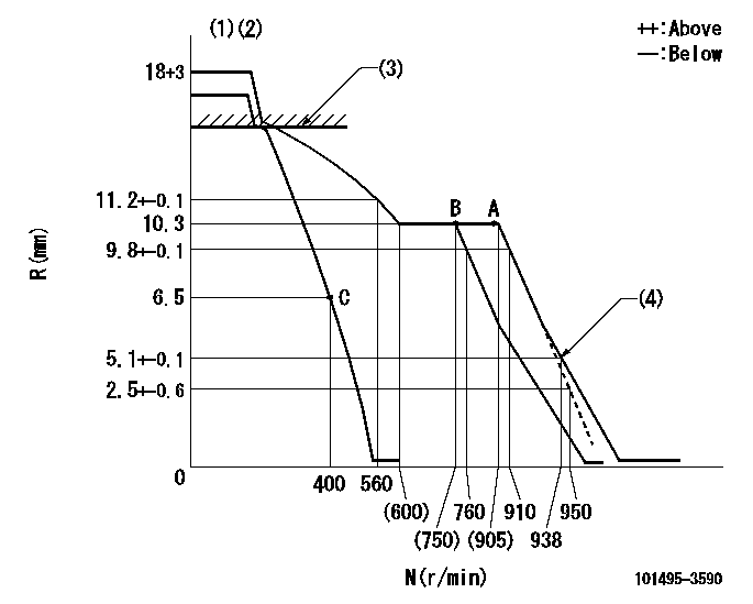
N:Pump speed
R:Rack position (mm)
(1)Target notch: K
(2)Tolerance for racks not indicated: +-0.05mm.
(3)RACK CAP: R1
(4)Set idle sub-spring
----------
K=10 R1=(17.5)mm
----------
----------
K=10 R1=(17.5)mm
----------
Speed control lever angle
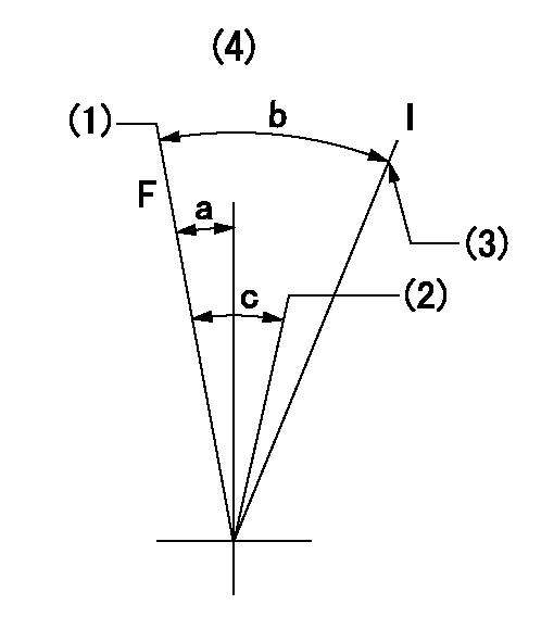
F:Full speed
I:Idle
(1)Set the pump speed at aa. ( At delivery )
(2)When pump speed set at bb
(3)Stopper bolt setting
(4)Use the hole above R = cc
----------
aa=910r/min bb=760r/min cc=60mm
----------
a=3deg+-5deg b=24deg+-5deg c=6deg+-5deg
----------
aa=910r/min bb=760r/min cc=60mm
----------
a=3deg+-5deg b=24deg+-5deg c=6deg+-5deg
Stop lever angle
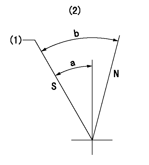
N:Pump normal
S:Stop the pump.
(1)Rack position = aa, speed = bb (stamp at delivery)
(2)No return spring
----------
aa=3-0.5mm bb=0r/min
----------
a=22.5deg+-5deg b=(50deg)
----------
aa=3-0.5mm bb=0r/min
----------
a=22.5deg+-5deg b=(50deg)
0000001501 I/P WITH LOAD PLUNGER ADJ
Load plunger-equipped pump adjustment
1. Adjust the variation between cylinders and the injection quantity.
2. At Full point A, adjust the pre-stroke to the specified value.
3. After pre-stroke adjustment, reconfirm that the fuel injection quantity and the variation between cylinders is as specified.
----------
----------
----------
----------
Timing setting

(1)Pump vertical direction
(2)Position of key groove at No 1 cylinder's beginning of injection
(3)Stamp aligning marks on the pump housing flange.
(4)After adjusting the injection quantity, adjust at rack position aa.
(5)-
----------
aa=10.3mm
----------
a=58deg+-3deg b=2deg+-30min
----------
aa=10.3mm
----------
a=58deg+-3deg b=2deg+-30min
Information:
The lubrication system consists of the suction tube, oil pump, cooler, filters, internal engine passages and the oil pan. The pan can be turned end-for-end to provide either a front or rear sump. The dipstick placement and suction tube length correspond with sump location. A longer suction tube and support is required when the pan is positioned for a rear sump.The oil pump draws lubricant from the sump and forces it through the oil cooler, oil filters, and then into the oil manifold. Oil flows through connecting passages to lubricate the engine components. A bypass valve in the pump controls the maximum pressure of the oil from the pump. As oil temperature increases, oil viscosity and pressure decreases and the oil filter bypass valve closes. Now, only filtered oil is delivered to the engine components. Oil temperature continues to increase and the oil cooler bypass valve closes. Oil now flows through the oil cooler and oil filter before reaching the engine components.A contaminated or restricted oil filter element will not prevent lubricating oil from being delivered to the engine components. The oil filter bypass valve will open, allowing oil to bypass the filter element.An oil manifold, cast into the cylinder block, directs lubricant to the camshaft journals and main bearing supply passages. Oil is also directed up through the cylinder head to lubricate the valve rocker arm shafts.The connecting rod bearings receive oil through drilled passages in the crankshaft between the main bearing journals and connecting rod journals.When the engine is warm and running at rated speed, the oil pressure gauge should register in the "operating range" (58 to 72 psi). A low pressure reading is normal at idling speeds.Some engines may be equipped with an auxiliary or remote mounted by-pass filter system. This system must be connected so part of the oil continuously circulates through the by-pass filter, from the crankcase lubricating oil pump. An orifice on the outlet or clean side of the filter restricts the flow of oil through the by-pass filter so that full oil pressure is available to all parts of the engine. Filtered oil from the by-pass filter is returned to the crankcase sump. The by-pass filter must never be used in place of the factory installed full flow filter.
COLD START
COLD START
Have questions with 101495-3590?
Group cross 101495-3590 ZEXEL
Komatsu
Komatsu
Komatsu
101495-3590
205711560
INJECTION-PUMP ASSEMBLY
S4D95LE-3
S4D95LE-3