Information injection-pump assembly
ZEXEL
101495-3580
1014953580
KOMATSU
6205711150
6205711150
Rating:
Cross reference number
ZEXEL
101495-3580
1014953580
KOMATSU
6205711150
6205711150
Zexel num
Bosch num
Firm num
Name
101495-3580
6205711150 KOMATSU
INJECTION-PUMP ASSEMBLY
S4D95LE-2 K
S4D95LE-2 K
Calibration Data:
Adjustment conditions
Test oil
1404 Test oil ISO4113 or {SAEJ967d}
1404 Test oil ISO4113 or {SAEJ967d}
Test oil temperature
degC
40
40
45
Nozzle and nozzle holder
105780-8140
Bosch type code
EF8511/9A
Nozzle
105780-0000
Bosch type code
DN12SD12T
Nozzle holder
105780-2080
Bosch type code
EF8511/9
Opening pressure
MPa
17.2
Opening pressure
kgf/cm2
175
Injection pipe
Outer diameter - inner diameter - length (mm) mm 6-2-600
Outer diameter - inner diameter - length (mm) mm 6-2-600
Tester oil delivery pressure
kPa
157
157
157
Tester oil delivery pressure
kgf/cm2
1.6
1.6
1.6
Direction of rotation (viewed from drive side)
Right R
Right R
Injection timing adjustment
Direction of rotation (viewed from drive side)
Right R
Right R
Injection order
1-2-4-3
Pre-stroke
mm
3.2
3.15
3.25
Beginning of injection position
Drive side NO.1
Drive side NO.1
Difference between angles 1
Cyl.1-2 deg. 90 89.5 90.5
Cyl.1-2 deg. 90 89.5 90.5
Difference between angles 2
Cal 1-4 deg. 180 179.5 180.5
Cal 1-4 deg. 180 179.5 180.5
Difference between angles 3
Cal 1-3 deg. 270 269.5 270.5
Cal 1-3 deg. 270 269.5 270.5
Injection quantity adjustment
Adjusting point
A
Rack position
11.7
Pump speed
r/min
900
900
900
Average injection quantity
mm3/st.
83
82
84
Max. variation between cylinders
%
0
-2.5
2.5
Basic
*
Fixing the lever
*
Injection quantity adjustment_02
Adjusting point
C
Rack position
8+-0.5
Pump speed
r/min
400
400
400
Average injection quantity
mm3/st.
8
7
9
Max. variation between cylinders
%
0
-15
15
Fixing the rack
*
Test data Ex:
Governor adjustment
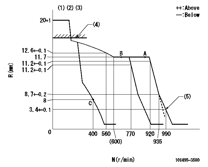
N:Pump speed
R:Rack position (mm)
(1)Target notch: K
(2)Tolerance for racks not indicated: +-0.05mm.
(3)At governor adjustment, set the stop lever at the normal position.
(4)RACK CAP: R1
(5)Set idle sub-spring
----------
K=7 R1=(17.5)mm
----------
----------
K=7 R1=(17.5)mm
----------
Speed control lever angle
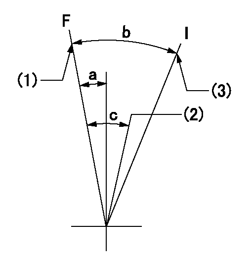
F:Full speed
I:Idle
(1)Set the pump speed at aa. ( At delivery )
(2)Set the pump speed at bb.
(3)Stopper bolt setting
----------
aa=920r/min bb=770r/min
----------
a=2deg+-5deg b=22deg+-5deg c=6deg+-5deg
----------
aa=920r/min bb=770r/min
----------
a=2deg+-5deg b=22deg+-5deg c=6deg+-5deg
Stop lever angle
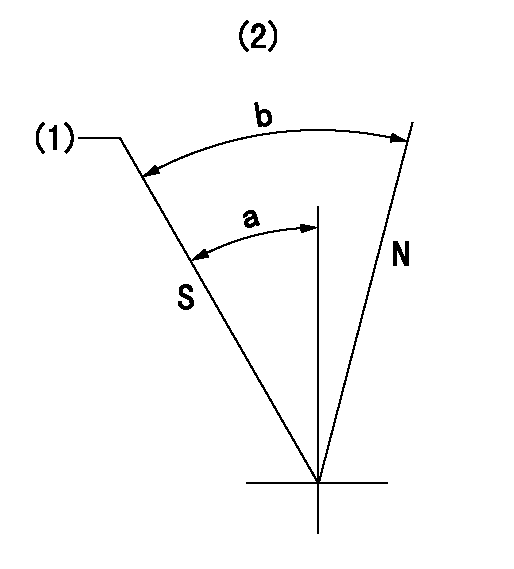
N:Pump normal
S:Stop the pump.
(1)Rack position = aa, speed = bb (stamp at delivery)
(2)No return spring
----------
aa=1-0.5mm bb=0r/min
----------
a=27.5deg+-5deg b=(55deg)
----------
aa=1-0.5mm bb=0r/min
----------
a=27.5deg+-5deg b=(55deg)
Timing setting

(1)Pump vertical direction
(2)Position of key groove at No 1 cylinder's beginning of injection
(3)Stamp aligning marks on the pump housing flange.
(4)-
(5)-
----------
----------
a=58deg+-3deg b=2deg+-30min
----------
----------
a=58deg+-3deg b=2deg+-30min
Information:
The fuel system consists of the transfer pump, fuel filter, shutoff solenoid, injection pumps, timing advance unit, governor, injection lines, nozzles and excess fuel return lines.The diaphragm-type fuel transfer pump mounts on the fuel injection pump housing and is driven by a lobe on the injection pump camshaft. The pump draws fuel from the vehicle supply tank and delivers it to a spin-on throw-away type filter. The filter is a combination primary-secondary element.Filtered fuel flows through a fuel shutoff solenoid, mounted on the fuel injection pump housing, into a fuel manifold. The solenoid operates electrically and stops fuel flow when the vehicle ignition system is off.Fuel in the manifold flows through the barrel assembly inlet port into the area above the injection pump plunger. During injection, the camshaft forces the plunger upward in the barrel. The end of the plunger closes the inlet port and forces the fuel out through high pressure injection lines to the nozzles.The injection nozzles are located under the valve cover and are held in place by clamps. The nozzle tip projects from the head into the cylinder bore. Atomized fuel is sprayed in a cone-shaped pattern through four orifices into the cylinder.During injection, a small amount of fuel leaks past the valve guide in the nozzle body to lubricate its moving parts. Any excess leakage flows from the nozzle to a fuel return manifold under the valve cover of each cylinder head. External lines connect the manifolds and return the fuel to the tank.Fuel Injection Pump Operation
Fuel enters the fuel injection pump housing from the fuel filter through the
Fuel enters the fuel injection pump housing from the fuel filter through the
Have questions with 101495-3580?
Group cross 101495-3580 ZEXEL
Komatsu
Komatsu
Komatsu
101495-3580
6205711150
INJECTION-PUMP ASSEMBLY
S4D95LE-2
S4D95LE-2