Information injection-pump assembly
ZEXEL
101495-3570
1014953570
KOMATSU
6204711150
6204711150
Rating:
Cross reference number
ZEXEL
101495-3570
1014953570
KOMATSU
6204711150
6204711150
Zexel num
Bosch num
Firm num
Name
101495-3570
6204711150 KOMATSU
INJECTION-PUMP ASSEMBLY
4D95LE-2/ K
4D95LE-2/ K
Calibration Data:
Adjustment conditions
Test oil
1404 Test oil ISO4113 or {SAEJ967d}
1404 Test oil ISO4113 or {SAEJ967d}
Test oil temperature
degC
40
40
45
Nozzle and nozzle holder
105780-8140
Bosch type code
EF8511/9A
Nozzle
105780-0000
Bosch type code
DN12SD12T
Nozzle holder
105780-2080
Bosch type code
EF8511/9
Opening pressure
MPa
17.2
Opening pressure
kgf/cm2
175
Injection pipe
Outer diameter - inner diameter - length (mm) mm 6-2-600
Outer diameter - inner diameter - length (mm) mm 6-2-600
Tester oil delivery pressure
kPa
157
157
157
Tester oil delivery pressure
kgf/cm2
1.6
1.6
1.6
Direction of rotation (viewed from drive side)
Right R
Right R
Injection timing adjustment
Direction of rotation (viewed from drive side)
Right R
Right R
Injection order
1-2-4-3
Pre-stroke
mm
3.2
3.15
3.25
Beginning of injection position
Drive side NO.1
Drive side NO.1
Difference between angles 1
Cyl.1-2 deg. 90 89.5 90.5
Cyl.1-2 deg. 90 89.5 90.5
Difference between angles 2
Cal 1-4 deg. 180 179.5 180.5
Cal 1-4 deg. 180 179.5 180.5
Difference between angles 3
Cal 1-3 deg. 270 269.5 270.5
Cal 1-3 deg. 270 269.5 270.5
Injection quantity adjustment
Adjusting point
A
Rack position
10.9
Pump speed
r/min
900
900
900
Average injection quantity
mm3/st.
67.5
66.5
68.5
Max. variation between cylinders
%
0
-2.5
2.5
Basic
*
Fixing the lever
*
Injection quantity adjustment_02
Adjusting point
-
Rack position
8.5+-0.5
Pump speed
r/min
400
400
400
Average injection quantity
mm3/st.
8
7
9
Max. variation between cylinders
%
0
-15
15
Fixing the rack
*
Remarks
Adjust only variation between cylinders; adjust governor according to governor specifications.
Adjust only variation between cylinders; adjust governor according to governor specifications.
Test data Ex:
Governor adjustment
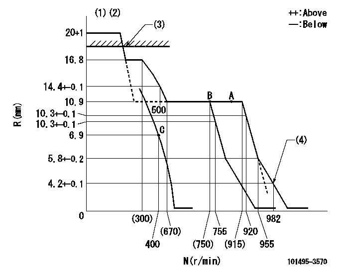
N:Pump speed
R:Rack position (mm)
(1)Target notch: K
(2)Tolerance for racks not indicated: +-0.05mm.
(3)RACK CAP: R1
(4)Set idle sub-spring
----------
K=12 R1=(17.5)mm
----------
----------
K=12 R1=(17.5)mm
----------
Speed control lever angle
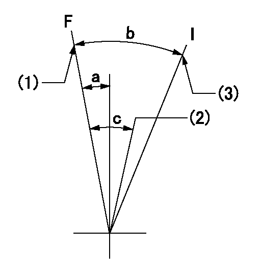
F:Full speed
I:Idle
(1)Set the pump speed at aa. ( At delivery )
(2)Set the pump speed at bb.
(3)Stopper bolt setting
----------
aa=920r/min bb=755r/min
----------
a=4deg+-5deg b=25deg+-5deg c=6deg+-5deg
----------
aa=920r/min bb=755r/min
----------
a=4deg+-5deg b=25deg+-5deg c=6deg+-5deg
Stop lever angle
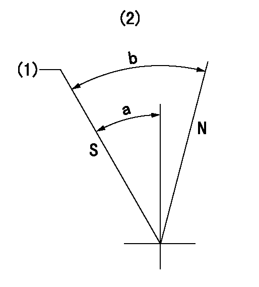
N:Pump normal
S:Stop the pump.
(1)Rack position = aa, speed = bb (stamp at delivery)
(2)No return spring
----------
aa=1-0.5mm bb=0r/min
----------
a=27.5deg+-5deg b=(55deg)
----------
aa=1-0.5mm bb=0r/min
----------
a=27.5deg+-5deg b=(55deg)
Timing setting

(1)Pump vertical direction
(2)Position of key groove at No 1 cylinder's beginning of injection
(3)Stamp aligning marks on the pump housing flange.
(4)-
(5)-
----------
----------
a=58deg+-3deg b=2deg+-30min
----------
----------
a=58deg+-3deg b=2deg+-30min
Information:
To many, the diesel principle may not be new, however, the special features of Caterpillar Diesel Truck Engines require that the operator and the maintenance personnel become acquainted with the systems in order to give the engine the best possible care. Maximum engine life depends a great deal on a good maintenance schedule performed by reliable personnel with a basic understanding of the working principles and systems.Diesel Engine Principle
This diesel engine operates on the reciprocating piston 4-stroke cycle, compression ignition principle, and burns fuels commercially known as diesel fuels. The basic differences between the spark ignition engine and the diesel engine are; the method of introducing fuel into the system and the method by which the fuel is ignited.The engine always takes a full charge of air into a cylinder on each inlet stroke, compresses it in an extremely small space causing the air to reach temperatures over 1000°F (537°C.). Fuel is injected into the cylinder as the piston nears the top of the compression stroke, where it mixes with the compressed air, and immediately starts to burn. This is called self-ignition, or spontaneous ignition. The expansion of the burning gases forces the piston down on a power stroke. Four Stroke Cycle Principle
The four stroke cycle engine has separate strokes for each basic function. The four strokes and the order in which they occur are: Intake, compression, power and exhaust.It must be remembered that for the four stroke cycle to function the inlet valves, exhaust valves and fuel injection must be timed in proper sequence with the piston. This is accomplished by timing gears between the crankshaft, the valve train and injection pumps. Intake Stroke: As the piston moves down on the inlet stroke, the inlet valve is opened and exhaust valve is closed by the camshaft and rocker arm arrangement. Air is drawn in through the air cleaner and intake valve by the partial vacuum caused by the piston traveling downward. Compression Stroke: At the end of the intake stroke the inlet valve closes and the exhaust valve remains closed. As the piston moves up, the air is compressed into an extremely small space causing the air temperature to rise high enough to ignite fuel. As the piston reaches near the top of the stroke, a measured amount of fuel is injected into the cylinder where it mixes with the compressed air and ignition begins. The atomized and burning fuel then rushes throughout the cylinder above the piston for complete combustion. Power Stroke: The piston is forced down by the pressure of the expanding and burning gases in the cylinder above the piston. During this power stroke, the intake and exhaust valves are closed. Exhaust Stroke: When the piston reaches the bottom of the power stroke the cylinder is filled with burned gases which must be expelled. As the piston begins its upward travel on the exhaust stroke, the exhaust valve is opened by the exhaust lobe on the cam. As the piston moves up, it forces
Have questions with 101495-3570?
Group cross 101495-3570 ZEXEL
Komatsu
Komatsu
Komatsu
101495-3570
6204711150
INJECTION-PUMP ASSEMBLY
4D95LE-2/
4D95LE-2/