Information injection-pump assembly
ZEXEL
101495-3561
1014953561
KOMATSU
6205711550
6205711550
Rating:
Cross reference number
ZEXEL
101495-3561
1014953561
KOMATSU
6205711550
6205711550
Zexel num
Bosch num
Firm num
Name
101495-3561
6205711550 KOMATSU
INJECTION-PUMP ASSEMBLY
S4D95LE-3
S4D95LE-3
Calibration Data:
Adjustment conditions
Test oil
1404 Test oil ISO4113 or {SAEJ967d}
1404 Test oil ISO4113 or {SAEJ967d}
Test oil temperature
degC
40
40
45
Nozzle and nozzle holder
105780-8140
Bosch type code
EF8511/9A
Nozzle
105780-0000
Bosch type code
DN12SD12T
Nozzle holder
105780-2080
Bosch type code
EF8511/9
Opening pressure
MPa
17.2
Opening pressure
kgf/cm2
175
Injection pipe
Outer diameter - inner diameter - length (mm) mm 6-2-600
Outer diameter - inner diameter - length (mm) mm 6-2-600
Tester oil delivery pressure
kPa
157
157
157
Tester oil delivery pressure
kgf/cm2
1.6
1.6
1.6
Direction of rotation (viewed from drive side)
Right R
Right R
Injection timing adjustment
Direction of rotation (viewed from drive side)
Right R
Right R
Injection order
1-2-4-3
Pre-stroke
mm
3.2
3.15
3.25
Rack position
After adjusting injection quantity. R=A
After adjusting injection quantity. R=A
Beginning of injection position
Drive side NO.1
Drive side NO.1
Difference between angles 1
Cyl.1-2 deg. 90 89.5 90.5
Cyl.1-2 deg. 90 89.5 90.5
Difference between angles 2
Cal 1-4 deg. 180 179.5 180.5
Cal 1-4 deg. 180 179.5 180.5
Difference between angles 3
Cal 1-3 deg. 270 269.5 270.5
Cal 1-3 deg. 270 269.5 270.5
Injection quantity adjustment
Adjusting point
A
Rack position
9.3
Pump speed
r/min
1075
1075
1075
Average injection quantity
mm3/st.
74
73
75
Max. variation between cylinders
%
0
-2.5
2.5
Basic
*
Fixing the lever
*
Boost pressure
kPa
46.7
46.7
Boost pressure
mmHg
350
350
Injection quantity adjustment_02
Adjusting point
-
Rack position
7.7+-0.5
Pump speed
r/min
440
440
440
Average injection quantity
mm3/st.
13.5
12.5
14.5
Max. variation between cylinders
%
0
-15
15
Fixing the rack
*
Boost pressure
kPa
0
0
0
Boost pressure
mmHg
0
0
0
Remarks
Adjust only variation between cylinders; adjust governor according to governor specifications.
Adjust only variation between cylinders; adjust governor according to governor specifications.
Injection quantity adjustment_03
Adjusting point
E
Rack position
-
Pump speed
r/min
100
100
100
Average injection quantity
mm3/st.
62
52
72
Fixing the lever
*
Boost pressure
kPa
0
0
0
Boost pressure
mmHg
0
0
0
Remarks
Rack cap
Rack cap
Boost compensator adjustment
Pump speed
r/min
500
500
500
Rack position
8.7
Boost pressure
kPa
6.7
4
9.4
Boost pressure
mmHg
50
30
70
Boost compensator adjustment_02
Pump speed
r/min
500
500
500
Rack position
8.9
Boost pressure
kPa
14.7
12
17.4
Boost pressure
mmHg
110
90
130
Boost compensator adjustment_03
Pump speed
r/min
500
500
500
Rack position
(9.3)
Boost pressure
kPa
33.3
33.3
33.3
Boost pressure
mmHg
250
250
250
Test data Ex:
Governor adjustment
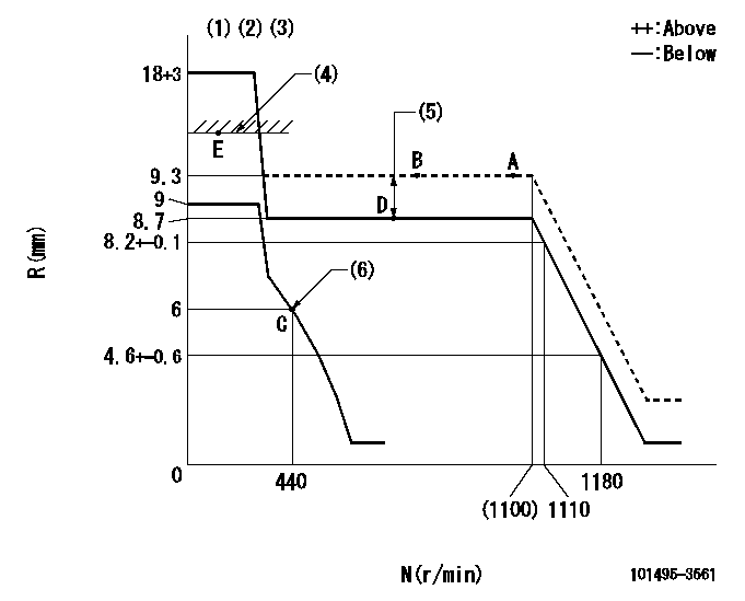
N:Pump speed
R:Rack position (mm)
(1)Target notch: K
(2)Tolerance for racks not indicated: +-0.05mm.
(3)Deliver without the torque control spring operating.
(4)RACK CAP: R1
(5)Boost compensator stroke: BCL
(6)Set idle sub-spring
----------
K=9 R1=(17.5)mm BCL=(0.6)mm
----------
----------
K=9 R1=(17.5)mm BCL=(0.6)mm
----------
Speed control lever angle
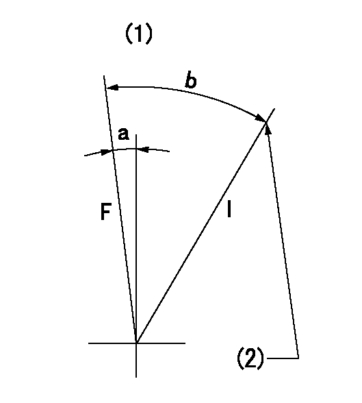
F:Full speed
I:Idle
(1)Use the hole at R = aa
(2)Stopper bolt setting
----------
aa=60mm
----------
a=2deg+-5deg b=21deg+-5deg
----------
aa=60mm
----------
a=2deg+-5deg b=21deg+-5deg
Stop lever angle
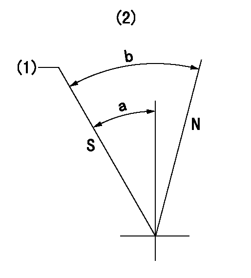
N:Pump normal
S:Stop the pump.
(1)Rack position = aa, speed = bb (stamp at delivery)
(2)No return spring
----------
aa=1-0.5mm bb=0r/min
----------
a=27.5deg+-5deg b=(55deg)
----------
aa=1-0.5mm bb=0r/min
----------
a=27.5deg+-5deg b=(55deg)
0000001501 TAMPER PROOF
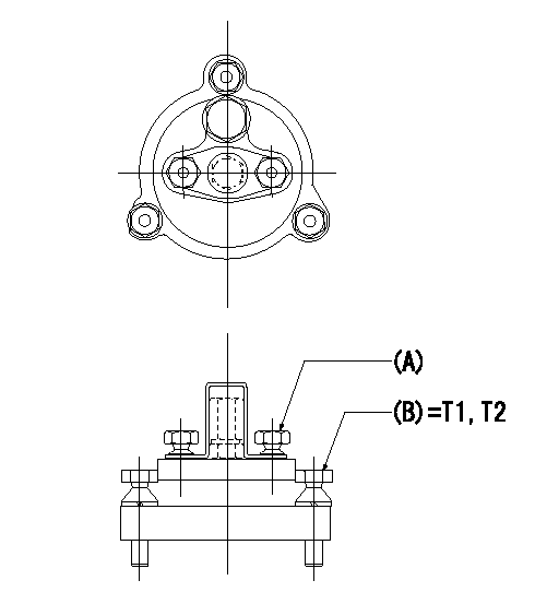
Tamperproofing-equipped boost compensator cover installation procedure
(A): After adjusting the boost compensator, assemble then tighten the bolts to remove the heads.
(B): Specified torque
(1)Before adjusting the governor and the boost compensator, tighten the screw to the specified torque.
(Tightening torque T = T1 maximum)
(2)After adjusting the governor and the boost compensator, tighten to the specified torque to break off the bolt heads.
(Tightening torque T = T2)
----------
T1=2.5N-m(0.25kgf-m) T2=2.9~4.4N-m(0.3~0.45kgf-m)
----------
----------
T1=2.5N-m(0.25kgf-m) T2=2.9~4.4N-m(0.3~0.45kgf-m)
----------
0000001601 I/P WITH LOAD PLUNGER ADJ
Load plunger-equipped pump adjustment
1. Adjust the variation between cylinders and the injection quantity.
2. At Full point A, adjust the pre-stroke to the specified value.
3. After pre-stroke adjustment, reconfirm that the fuel injection quantity and the variation between cylinders is as specified.
----------
----------
----------
----------
Timing setting

(1)Pump vertical direction
(2)Position of key groove at No 1 cylinder's beginning of injection
(3)Stamp aligning marks on the pump housing flange.
(4)B.T.D.C.: aa
(5)After adjusting the injection quantity, adjust at rack position bb.
----------
aa=6deg bb=9.3mm
----------
a=58deg+-3deg b=2deg+-30min
----------
aa=6deg bb=9.3mm
----------
a=58deg+-3deg b=2deg+-30min
Information:
The following topics describe care and maintenance of the electrical system components. These components functioning together produce the energy needed for operating the electrical equipment on the truck and each is dependent upon the other for satisfactory operation. In the event of failure or improper operation, it is essential to check the entire electrical system as a defect in one component can cause damage to another.Many electrical system problems can be traced to loose or corroded connections. Keep connections tight and make sure the wiring insulation is in satisfactory condition. Most of electrical system testing can be performed on the vehicle. (It should be remembered, if a malfunction is found on a vehicle test, the component may need further testing, repair or replacement.) Installations will have electrical components not furnished by Caterpillar. Consult the vehicle manufacturer's manual for maintenance procedures.Check the electrolyte level of each cell and the general condition of the battery. Maintain the electrolyte level to the base of each vent well. The make-up water must be one of the following (in order of preference): 1. Distilled water.2. Odorless, tasteless drinking water.3. Iron free water.4. Any available water.
Never add acid or electrolyte.
CLEANING BATTERY: Mix a weak solution of baking soda and water. Be careful not to get cleaning solution into battery. Apply the solution with a soft bristle brush.
CLEANING BATTERY TERMINALSThoroughly rinse the battery and battery tray with clean water. Apply grease to the battery cable clamps and terminals and to all threads. Testing The Electrolyte Solution: The general condition of a battery can be determined by measuring the specific gravity of the electrolyte solution and adjusting the reading to 80°F (27°C). If the electrolyte level is too low to allow taking a hydrometer reading, add make-up water to the correct level and then charge the battery 2 to 4 hours before taking a reading.
TESTING ELECTROLYTE SOLUTION1. Insert the hydrometer into a cell. Fill the hydrometer barrel while holding it vertically. The float must not drag on the wall of the barrel.2. Read the hydrometer: 1.250 or above - fully charged battery cell1.250-1.225 - full to half charged battery cell1.225-1.150 - half to low charged battery cellBelow 1.150 - dead cell1.000 - water3. Test each cell in the same manner.4. If there is more than .050 (50 gravity points) variation between the highest and lowest reading, the battery may need to be replaced.5. Adjust the readings to 80°F (27°C). a. For every 10F° (5.5C°) the electrolyte temperature is above 80°F (27°C), add .004 (4 gravity points) to the specific gravity readings.b. For every 10F°(5.5C°) the electrolyte temperature is below 80°F (27°C), subtract .004 (4 gravity points) from the specific gravity reading.The corrected reading is of most importance during cold weather when the hydrometer reading is always corrected to a lower specific gravity reading. A low reading signifies the battery has less available power to crank the engine and that booster batteries may be required. Voltage Test (After Load): A load test should be made on a
Have questions with 101495-3561?
Group cross 101495-3561 ZEXEL
Komatsu
Komatsu
Komatsu
101495-3561
6205711550
INJECTION-PUMP ASSEMBLY
S4D95LE-3
S4D95LE-3