Information injection-pump assembly
ZEXEL
101495-3500
1014953500
Rating:
Cross reference number
ZEXEL
101495-3500
1014953500
Zexel num
Bosch num
Firm num
Name
101495-3500
INJECTION-PUMP ASSEMBLY
Calibration Data:
Adjustment conditions
Test oil
1404 Test oil ISO4113 or {SAEJ967d}
1404 Test oil ISO4113 or {SAEJ967d}
Test oil temperature
degC
40
40
45
Nozzle and nozzle holder
105780-8140
Bosch type code
EF8511/9A
Nozzle
105780-0000
Bosch type code
DN12SD12T
Nozzle holder
105780-2080
Bosch type code
EF8511/9
Opening pressure
MPa
17.2
Opening pressure
kgf/cm2
175
Injection pipe
Outer diameter - inner diameter - length (mm) mm 6-2-600
Outer diameter - inner diameter - length (mm) mm 6-2-600
Tester oil delivery pressure
kPa
157
157
157
Tester oil delivery pressure
kgf/cm2
1.6
1.6
1.6
Direction of rotation (viewed from drive side)
Right R
Right R
Injection timing adjustment
Direction of rotation (viewed from drive side)
Right R
Right R
Injection order
1-2-4-3
Pre-stroke
mm
3.2
3.15
3.25
Rack position
After adjusting injection quantity. R=A
After adjusting injection quantity. R=A
Beginning of injection position
Drive side NO.1
Drive side NO.1
Difference between angles 1
Cyl.1-2 deg. 90 89.5 90.5
Cyl.1-2 deg. 90 89.5 90.5
Difference between angles 2
Cal 1-4 deg. 180 179.5 180.5
Cal 1-4 deg. 180 179.5 180.5
Difference between angles 3
Cal 1-3 deg. 270 269.5 270.5
Cal 1-3 deg. 270 269.5 270.5
Injection quantity adjustment
Adjusting point
A
Rack position
10.8
Pump speed
r/min
925
925
925
Average injection quantity
mm3/st.
63
62
64
Max. variation between cylinders
%
0
-2.5
2.5
Basic
*
Fixing the lever
*
Injection quantity adjustment_02
Adjusting point
-
Rack position
8.3+-0.5
Pump speed
r/min
575
575
575
Average injection quantity
mm3/st.
8
7
9
Max. variation between cylinders
%
0
-15
15
Fixing the rack
*
Remarks
Adjust only variation between cylinders; adjust governor according to governor specifications.
Adjust only variation between cylinders; adjust governor according to governor specifications.
Test data Ex:
Governor adjustment
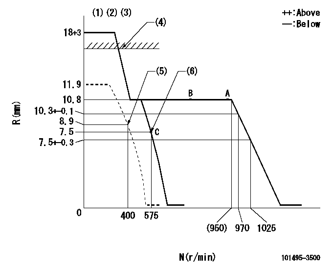
N:Pump speed
R:Rack position (mm)
(1)Target notch: K
(2)Tolerance for racks not indicated: +-0.05mm.
(3)Deliver without the torque control spring operating.
(4)RACK CAP: R1
(5)Set idle sub-spring
(6)Main spring setting
----------
K=6 R1=(17.5)mm
----------
----------
K=6 R1=(17.5)mm
----------
Speed control lever angle
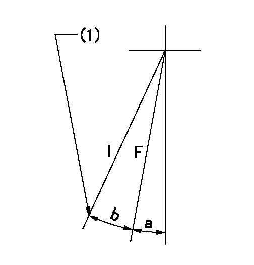
F:Full speed
I:Idle
(1)Stopper bolt setting
----------
----------
a=7deg+-5deg b=13deg+-5deg
----------
----------
a=7deg+-5deg b=13deg+-5deg
Stop lever angle
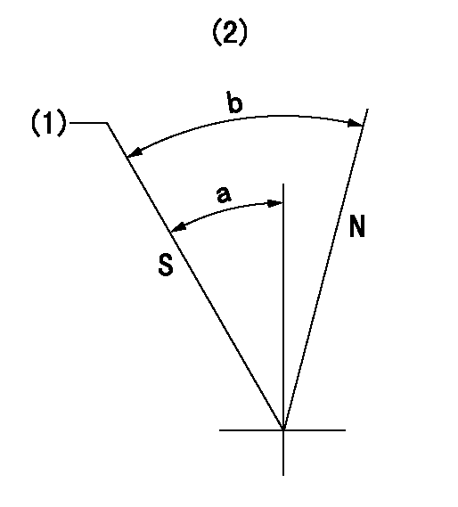
N:Pump normal
S:Stop the pump.
(1)Rack position = aa, speed = bb (stamp at delivery)
(2)No return spring
----------
aa=1-0.5mm bb=0r/min
----------
a=27.5deg+-5deg b=(55deg)
----------
aa=1-0.5mm bb=0r/min
----------
a=27.5deg+-5deg b=(55deg)
0000001501 I/P WITH LOAD PLUNGER ADJ
Load plunger-equipped pump adjustment
1. Adjust the variation between cylinders and the injection quantity.
2. At Full point A, adjust the pre-stroke to the specified value.
3. After pre-stroke adjustment, reconfirm that the fuel injection quantity and the variation between cylinders is as specified.
----------
----------
----------
----------
Timing setting

(1)Pump vertical direction
(2)Position of key groove at No 1 cylinder's beginning of injection
(3)Stamp aligning marks on the pump housing flange.
(4)After adjusting the injection quantity, adjust at rack position aa.
(5)-
----------
aa=10.8mm
----------
a=58deg+-3deg b=2deg+-30min
----------
aa=10.8mm
----------
a=58deg+-3deg b=2deg+-30min
Information:
This engine has a pressurized cooling system. Coolant is circulated by a belt driven, centrifugal type water pump. A water temperature regulator, located at the left front of the cylinder head, restricts coolant flow through the radiator until the coolant reaches operating temperature.The water pump has two outlets. One outlet directs coolant through a passage in the water temperature regulator housing to the aftercooler, to lower the temperature of inlet air in the inlet manifold. The other water outlet directs coolant through a water manifold in the side of the cylinder block, to cool engine lubricating oil. Coolant flows from the water manifold around the cylinder liners, into the cylinder head and around the precombustion chambers. Both streams of water join at the water temperature regulator. The water cooled air compressor receives coolant through a tube that is connected to the water manifold in the side of the cylinder block. Coolant returns through a tube from the air compressor head to the diesel engine cylinder head.Until the coolant reaches the temperature required to open the temperature regulator, coolant bypasses the radiator and flows directly back to the water pump.When the coolant reaches the temperature required to open the temperature regulator, coolant is then directed through the radiator.A pressure relief cap assembly is used to control the pressure in the cooling system, and prevents loss of coolant through the radiator overflow tube.Pressurizing the cooling system serves two purposes. First, it permits safe operation at coolant temperatures higher than the normal boiling point, providing a margin of cooling for intermittent peak loads. Secondly, it prevents cavitation in the water pump, and reduces the possibility of air or steam pockets forming in the coolant passages. Proper operation of the pressure relief cap assembly is essential. A pressure relief cap allows pressure (and some water, if the cooling system is too full) to escape when the pressure in the cooling system exceeds the capacity of the pressure cap. Loss of pressure will cause steam to form when coolant temperature is above the normal boiling point.Water Pump
The centrifugal-type water pump has two seals, one prevents leakage of water and the other prevents leakage of lubricant.An opening in the bottom of the pump housing, allows any leakage at the water seal or the rear bearing oil seal to escape.Fan
The fan is driven by three V-belts, from a pulley on the crankshaft. Belt tension is adjusted by moving the bracket assembly which includes the fan mounting and pulley.Water Temperature Regulator
The water temperature regulator restricts the flow of coolant through the radiator, until the coolant reaches operating temperature; approximately 165°F (74°C.) The regulator is fully open at approximately 180°F (82°C.)The shunt cooling system is used in many truck installations. The shunt cooling system provides continuous circulation which helps prevent aeration and pump cavitation by maintaining a positive head of water at the pump inlet at all times. It differs from the conventional cooling system in that the radiator top tank is divided into two compartments (upper
Have questions with 101495-3500?
Group cross 101495-3500 ZEXEL
101495-3500
INJECTION-PUMP ASSEMBLY