Information injection-pump assembly
ZEXEL
101495-3480
1014953480
Rating:
Cross reference number
ZEXEL
101495-3480
1014953480
Zexel num
Bosch num
Firm num
Name
101495-3480
INJECTION-PUMP ASSEMBLY
Calibration Data:
Adjustment conditions
Test oil
1404 Test oil ISO4113 or {SAEJ967d}
1404 Test oil ISO4113 or {SAEJ967d}
Test oil temperature
degC
40
40
45
Nozzle and nozzle holder
105780-8140
Bosch type code
EF8511/9A
Nozzle
105780-0000
Bosch type code
DN12SD12T
Nozzle holder
105780-2080
Bosch type code
EF8511/9
Opening pressure
MPa
17.2
Opening pressure
kgf/cm2
175
Injection pipe
Outer diameter - inner diameter - length (mm) mm 6-2-600
Outer diameter - inner diameter - length (mm) mm 6-2-600
Tester oil delivery pressure
kPa
157
157
157
Tester oil delivery pressure
kgf/cm2
1.6
1.6
1.6
Direction of rotation (viewed from drive side)
Right R
Right R
Injection timing adjustment
Direction of rotation (viewed from drive side)
Right R
Right R
Injection order
1-2-4-3
Pre-stroke
mm
3.2
3.15
3.25
Rack position
After adjusting injection quantity. R=A
After adjusting injection quantity. R=A
Beginning of injection position
Drive side NO.1
Drive side NO.1
Difference between angles 1
Cyl.1-2 deg. 90 89.5 90.5
Cyl.1-2 deg. 90 89.5 90.5
Difference between angles 2
Cal 1-4 deg. 180 179.5 180.5
Cal 1-4 deg. 180 179.5 180.5
Difference between angles 3
Cal 1-3 deg. 270 269.5 270.5
Cal 1-3 deg. 270 269.5 270.5
Injection quantity adjustment
Adjusting point
A
Rack position
9.3
Pump speed
r/min
1300
1300
1300
Average injection quantity
mm3/st.
58.5
57.5
59.5
Max. variation between cylinders
%
0
-2.5
2.5
Basic
*
Fixing the lever
*
Injection quantity adjustment_02
Adjusting point
-
Rack position
7.8+-0.5
Pump speed
r/min
400
400
400
Average injection quantity
mm3/st.
8
7
9
Max. variation between cylinders
%
0
-10
10
Fixing the rack
*
Remarks
Adjust only variation between cylinders; adjust governor according to governor specifications.
Adjust only variation between cylinders; adjust governor according to governor specifications.
Test data Ex:
Governor adjustment
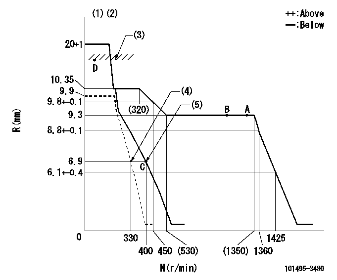
N:Pump speed
R:Rack position (mm)
(1)Target notch: K
(2)Tolerance for racks not indicated: +-0.05mm.
(3)RACK CAP
(4)Set idle sub-spring
(5)Main spring setting
----------
K=15
----------
----------
K=15
----------
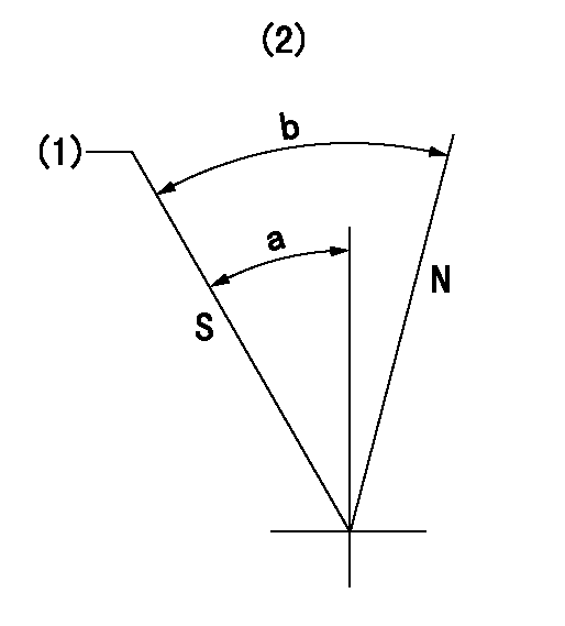
Speed control lever angle

F:Full speed
I:Idle
(1)Use the hole at R = aa
(2)Stopper bolt setting
----------
aa=60mm
----------
a=24deg+-5deg b=31deg+-5deg
----------
aa=60mm
----------
a=24deg+-5deg b=31deg+-5deg
Stop lever angle
N:Pump normal
S:Stop the pump.
(1)Rack position = aa, speed = bb (stamp at delivery)
(2)No return spring
----------
aa=1-0.5mm bb=0r/min
----------
a=27.5deg+-5deg b=(55deg)
----------
aa=1-0.5mm bb=0r/min
----------
a=27.5deg+-5deg b=(55deg)
0000001501 GOV FULL LOAD ADJUSTMENT
Load plunger-equipped pump adjustment
1. Adjust the variation between cylinders and the injection quantity.
2. At Full point A, adjust the pre-stroke to the specified value.
3. After pre-stroke adjustment, reconfirm that the fuel injection quantity and the variation between cylinders is as specified.
----------
----------
----------
----------
Timing setting

(1)Pump vertical direction
(2)Position of key groove at No 1 cylinder's beginning of injection
(3)Stamp aligning marks on the pump housing flange.
(4)After adjusting the injection quantity, adjust at rack position aa.
(5)-
----------
aa=9.3mm
----------
a=58deg+-3deg b=2deg+-30min
----------
aa=9.3mm
----------
a=58deg+-3deg b=2deg+-30min
Information:
AIR COMPRESSOR: The air compressor which supplies pressure air is a two cylinder unit and is gear driven. The moving parts are lubricated from the diesel engine crankcase lubricating oil system. The compressor is liquid cooled and is connected through lines to the diesel engine cooling system.Every 10,000 miles inspect air compressor air cleaner. The time to replace the air compressor air cleaner is determined by inspection. Install a new element if plugged or oil soaked. Replace element every 20,000 miles regardless of condition.
AIR COMPRESSOR AIR CLEANEREvery 100,000 miles rebuild or install a rebuilt or new air compressor. This component should be checked and rebuilt in a well equipped shop with proper tools and personnel familiar with disassembly and assembly procedures. Thoroughly inspect all connections for tightness before placing vehicle in use.DRAIN AIR TANKS: Drain moisture from the air storage tanks at the end of each days run. Open the drain cocks at the bottom of the tank. Some air systems have automatic moisture ejector valves which can also be operated manually. Refer to the truck manufacturer's manual for maintenance procedures.TIGHTEN ENGINE MOUNTING BOLTS: When giving the engine a seasonal check, tighten all mounting bolts and nuts. Replace damaged, broken or lost bolts. See BOLT, NUT AND TAPERLOCK STUD SPECIFICATIONS.Major Inspection Maintenance
These items are of major checks which require partial disassembly and should be performed by experienced personnel. If it is determined that parts are worn beyond limits, remove the engine and completely rebuild.Oil consumption, combustion gas blow by, loss of power, and other signs of wear should be taken into consideration and analyzed to determine if the engine can be operated for another service interval.CRANKSHAFT END CLEARANCE: When engine is being rebuilt or at the 200,000 mile interval, check the crankshaft end clearance. The check can be made by attaching a dial indicator against the crankshaft pulley or vibration damper while prying against the vibration damper and pulley hub. End clearance should not exceed .035 inches (0,89 mm). Do not pry against outer diameter of vibration damper.CRANKSHAFT SEALS: When engine is being rebuilt or at the 300,000 mile interval or if oil leakage is occuring, replace seals.REBUILD CYLINDER HEAD: Irregular engine operation and excessive white or blue smoke can be caused by leaky valves and/or worn valve guides. The cylinder head must be removed for further inspection and reconditioning. Your authorized dealer is equipped to analyze the problem and recondition the cylinder head and valve components.
Have questions with 101495-3480?
Group cross 101495-3480 ZEXEL
Komatsu
Komatsu
Komatsu
Komatsu
Komatsu
Komatsu
Komatsu
Komatsu
Komatsu
101495-3480
INJECTION-PUMP ASSEMBLY