Information injection-pump assembly
ZEXEL
101495-3421
1014953421
Rating:
Cross reference number
ZEXEL
101495-3421
1014953421
Zexel num
Bosch num
Firm num
Name
101495-3421
INJECTION-PUMP ASSEMBLY
Calibration Data:
Adjustment conditions
Test oil
1404 Test oil ISO4113 or {SAEJ967d}
1404 Test oil ISO4113 or {SAEJ967d}
Test oil temperature
degC
40
40
45
Nozzle and nozzle holder
105780-8140
Bosch type code
EF8511/9A
Nozzle
105780-0000
Bosch type code
DN12SD12T
Nozzle holder
105780-2080
Bosch type code
EF8511/9
Opening pressure
MPa
17.2
Opening pressure
kgf/cm2
175
Injection pipe
Outer diameter - inner diameter - length (mm) mm 6-2-600
Outer diameter - inner diameter - length (mm) mm 6-2-600
Tester oil delivery pressure
kPa
157
157
157
Tester oil delivery pressure
kgf/cm2
1.6
1.6
1.6
Direction of rotation (viewed from drive side)
Right R
Right R
Injection timing adjustment
Direction of rotation (viewed from drive side)
Right R
Right R
Injection order
1-2-4-3
Pre-stroke
mm
3.2
3.15
3.25
Beginning of injection position
Drive side NO.1
Drive side NO.1
Difference between angles 1
Cyl.1-2 deg. 90 89.5 90.5
Cyl.1-2 deg. 90 89.5 90.5
Difference between angles 2
Cal 1-4 deg. 180 179.5 180.5
Cal 1-4 deg. 180 179.5 180.5
Difference between angles 3
Cal 1-3 deg. 270 269.5 270.5
Cal 1-3 deg. 270 269.5 270.5
Injection quantity adjustment
Adjusting point
A
Rack position
10.6
Pump speed
r/min
900
900
900
Average injection quantity
mm3/st.
63.5
62.5
64.5
Max. variation between cylinders
%
0
-2.5
2.5
Basic
*
Fixing the rack
*
Injection quantity adjustment_02
Adjusting point
-
Rack position
8.4+-0.5
Pump speed
r/min
400
400
400
Average injection quantity
mm3/st.
8
7
9
Max. variation between cylinders
%
0
-15
15
Fixing the rack
*
Remarks
Adjust only variation between cylinders; adjust governor according to governor specifications.
Adjust only variation between cylinders; adjust governor according to governor specifications.
Test data Ex:
Governor adjustment
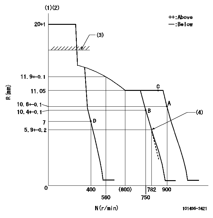
N:Pump speed
R:Rack position (mm)
(1)Target notch: K
(2)Tolerance for racks not indicated: +-0.05mm.
(3)RACK CAP: R1
(4)Idle sub spring setting: L1.
----------
K=15 R1=(17.5)mm L1=5.9-0.5mm
----------
----------
K=15 R1=(17.5)mm L1=5.9-0.5mm
----------
Speed control lever angle
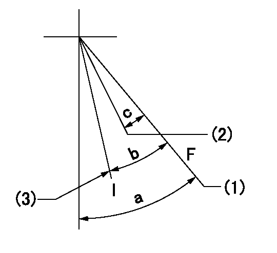
F:Full speed
I:Idle
(1)Set the pump speed at aa. ( At delivery )
(2)Set the pump speed at bb.
(3)Stopper bolt setting
----------
aa=900r/min bb=750r/min
----------
a=49deg+-5deg b=24deg+-5deg c=7deg+-5deg
----------
aa=900r/min bb=750r/min
----------
a=49deg+-5deg b=24deg+-5deg c=7deg+-5deg
Stop lever angle
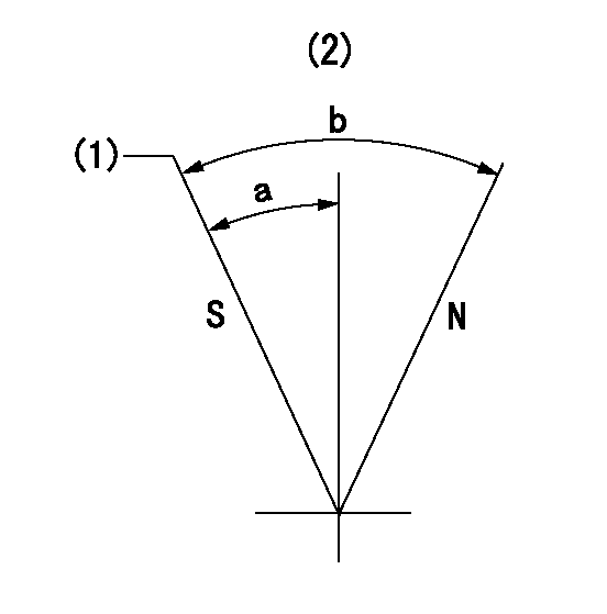
N:Pump normal
S:Stop the pump.
(1)Rack position = aa, speed = bb (stamp at delivery)
(2)No return spring
----------
aa=1-0.5mm bb=0r/min
----------
a=27.5deg+-5deg b=(55deg)
----------
aa=1-0.5mm bb=0r/min
----------
a=27.5deg+-5deg b=(55deg)
Timing setting
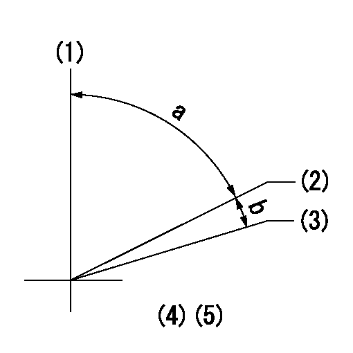
(1)Pump vertical direction
(2)Position of key groove at No 1 cylinder's beginning of injection
(3)Stamp aligning marks on the pump housing flange.
(4)-
(5)-
----------
----------
a=58deg+-3deg b=2deg+-30min
----------
----------
a=58deg+-3deg b=2deg+-30min
Information:
Introduction
This technical bulletin pertains to balancing the lubrication to the pin joints on the 994F Wheel Loader.Problem
There is a lack of lubrication to the A-pin.Solution
Increase the amount of grease to the A-pin by decreasing the interval of the lube cycle from 15 minutes (factory setting) to 8 minutes. Decrease the cycle time to 8 minutes by using the VIMS keypad.Adjust the injectors at all other pin joints in order to reduce the grease flow. This will prevent having excess grease at the other pin joints.See the table for each injector setting.
Table 1
Pin Joint Location # Injectors Number of Turns Out Lubricant Volume (in3) Lubricant Volume (mL) mL/Hour
0 0.014 0.2294 0.0000
Hitches (2)
Trunnions (4)
Fan Drive/Belt (2) 8 1 0.022 0.3605 21.6309
F (2)
G (2) 4 2 0.030 0.4916 14.7484
E (2)
Steering Cylinders (4) 6 3 0.038 0.6227 28.0219
B (4)
C (2)
D (2)
K (2)
Y (2) 12 4 0.046 0.7538 67.8424
5 0.054 0.8849 0.0000
6 0.062 1.0160 0.0000
7 0.070 1.1471 0.0000
A (4) 4 8 0.078 1.2782 38.3457
Total mL/Hour 170.5893
Have questions with 101495-3421?
Group cross 101495-3421 ZEXEL
101495-3421
INJECTION-PUMP ASSEMBLY