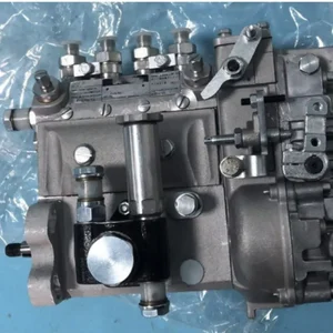
Information injection-pump assembly
BOSCH
9 400 610 559
9400610559
ZEXEL
101495-3380
1014953380
KOMATSU
6204731310
6204731310

Rating:
Compare Prices: .
As an associate, we earn commssions on qualifying purchases through the links below

Fuel Injection Pump 6204-73-1310 6204-73-1240 for Komatsu Engine 4D95L
100% Apollo part number:6204-73-1310 6204-73-1240 || application: for Komatsu Engine 4D95L
100% Apollo part number:6204-73-1310 6204-73-1240 || application: for Komatsu Engine 4D95L

VIIKEND Fuel Injection Pump 101049-8760 6204-73-1310 Compatible with Komatsu Engine 4D95L 4D95LE 4D95L-1FF 4D95L-1GG 4D95LE-1B-B
VIIKEND Part Name: Fuel Injection Pump || Part Number: 101049-8760 6204-73-1310 Note: Please check the fitment carefully before purchase. Or just tell us the part number you need. || Engine Model: 4D95L || Applicable: Compatible with Komatsu Engine 4D95L 4D95LE 4D95L-1FF 4D95L-1GG 4D95LE-1B-B || Package included: 1pcs Fuel Injection Pump 101049-8760 6204-73-1310
VIIKEND Part Name: Fuel Injection Pump || Part Number: 101049-8760 6204-73-1310 Note: Please check the fitment carefully before purchase. Or just tell us the part number you need. || Engine Model: 4D95L || Applicable: Compatible with Komatsu Engine 4D95L 4D95LE 4D95L-1FF 4D95L-1GG 4D95LE-1B-B || Package included: 1pcs Fuel Injection Pump 101049-8760 6204-73-1310

IMIFAFTAbT 6204-73-1240 6204-73-1310 Fuel Injection Pump 6204731240 6204731310 for Komatsu 4D95L 4D95LE Engine
IMIFAFTAbT Part Name:Fuel Injection Pump 6204-73-1240 6204-73-1310 || Part Number:6204-73-1240 6204-73-1310 6204731240 6204731310 || APPlication: Compatible with Komatsu 4D95L 4D95LE Engine || If you are not sure if the product is suitable please leave us a message and send us your original || product picture and part number and we will send the correct part after confirmation
IMIFAFTAbT Part Name:Fuel Injection Pump 6204-73-1240 6204-73-1310 || Part Number:6204-73-1240 6204-73-1310 6204731240 6204731310 || APPlication: Compatible with Komatsu 4D95L 4D95LE Engine || If you are not sure if the product is suitable please leave us a message and send us your original || product picture and part number and we will send the correct part after confirmation
You can express buy:
USD 627.3
14-06-2025
14-06-2025
6204-73-1240 6204-73-1310 Fuel Injection Pump for Komatsu 4D95L 4D95LE Engine
Service parts 101495-3380 INJECTION-PUMP ASSEMBLY:
1.
_

5.
AUTOM. ADVANCE MECHANIS
6.
COUPLING PLATE
7.
COUPLING PLATE
8.
_
9.
_
11.
Nozzle and Holder
6202-13-3300
12.
Open Pre:MPa(Kqf/cm2)
22.1{225}

15.
NOZZLE SET
Cross reference number
BOSCH
9 400 610 559
9400610559
ZEXEL
101495-3380
1014953380
KOMATSU
6204731310
6204731310
Zexel num
Bosch num
Firm num
Name
9 400 610 559
6204731310 KOMATSU
INJECTION-PUMP ASSEMBLY
4D95LE * K 14BC INJECTION PUMP ASSY PE4A,5A, PE
4D95LE * K 14BC INJECTION PUMP ASSY PE4A,5A, PE
Calibration Data:
Adjustment conditions
Test oil
1404 Test oil ISO4113 or {SAEJ967d}
1404 Test oil ISO4113 or {SAEJ967d}
Test oil temperature
degC
40
40
45
Nozzle and nozzle holder
105780-8140
Bosch type code
EF8511/9A
Nozzle
105780-0000
Bosch type code
DN12SD12T
Nozzle holder
105780-2080
Bosch type code
EF8511/9
Opening pressure
MPa
17.2
Opening pressure
kgf/cm2
175
Injection pipe
Outer diameter - inner diameter - length (mm) mm 6-2-600
Outer diameter - inner diameter - length (mm) mm 6-2-600
Tester oil delivery pressure
kPa
157
157
157
Tester oil delivery pressure
kgf/cm2
1.6
1.6
1.6
Direction of rotation (viewed from drive side)
Right R
Right R
Injection timing adjustment
Direction of rotation (viewed from drive side)
Right R
Right R
Injection order
1-2-4-3
Pre-stroke
mm
3.6
3.55
3.65
Beginning of injection position
Drive side NO.1
Drive side NO.1
Difference between angles 1
Cyl.1-2 deg. 90 89.5 90.5
Cyl.1-2 deg. 90 89.5 90.5
Difference between angles 2
Cal 1-4 deg. 180 179.5 180.5
Cal 1-4 deg. 180 179.5 180.5
Difference between angles 3
Cal 1-3 deg. 270 269.5 270.5
Cal 1-3 deg. 270 269.5 270.5
Injection quantity adjustment
Adjusting point
A
Rack position
11.8
Pump speed
r/min
950
950
950
Average injection quantity
mm3/st.
45
44
46
Max. variation between cylinders
%
0
-2.5
2.5
Basic
*
Fixing the lever
*
Injection quantity adjustment_02
Adjusting point
-
Rack position
10+-0.5
Pump speed
r/min
500
500
500
Average injection quantity
mm3/st.
13
12
14
Max. variation between cylinders
%
0
-15
15
Fixing the rack
*
Remarks
Adjust only variation between cylinders; adjust governor according to governor specifications.
Adjust only variation between cylinders; adjust governor according to governor specifications.
Injection quantity adjustment_03
Adjusting point
D
Rack position
15+0.2
Pump speed
r/min
100
100
100
Average injection quantity
mm3/st.
56
46
66
Fixing the lever
*
Rack limit
*
Test data Ex:
Governor adjustment
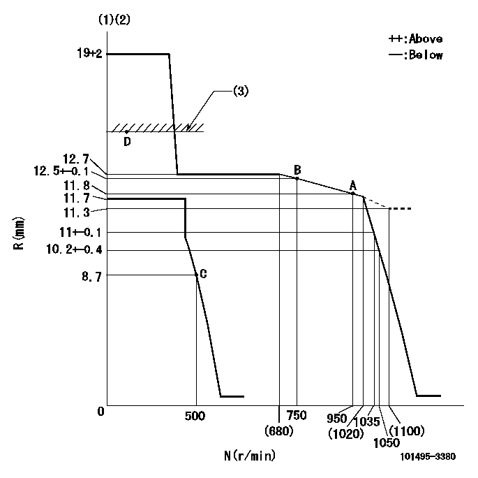
N:Pump speed
R:Rack position (mm)
(1)Target notch: K
(2)Tolerance for racks not indicated: +-0.05mm.
(3)RACK LIMIT: RAL
----------
K=10 RAL=15+0.2mm
----------
----------
K=10 RAL=15+0.2mm
----------
Speed control lever angle
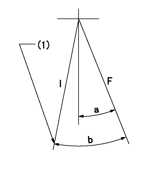
F:Full speed
I:Idle
(1)Stopper bolt setting
----------
----------
a=(2deg)+-5deg b=(22deg)+-5deg
----------
----------
a=(2deg)+-5deg b=(22deg)+-5deg
Stop lever angle
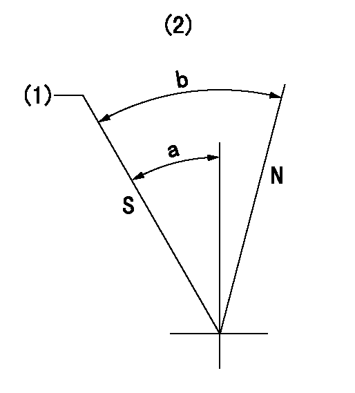
N:Pump normal
S:Stop the pump.
(1)Rack position = aa, speed = bb (stamp at delivery)
(2)No return spring
----------
aa=1-0.5mm bb=0r/min
----------
a=27.5deg+-5deg b=(55deg)
----------
aa=1-0.5mm bb=0r/min
----------
a=27.5deg+-5deg b=(55deg)
Timing setting

(1)Pump vertical direction
(2)Position of key groove at No 1 cylinder's beginning of injection
(3)Stamp aligning marks on the pump housing flange.
(4)-
----------
----------
a=59deg36min+-3deg b=0deg24min+-30min
----------
----------
a=59deg36min+-3deg b=0deg24min+-30min
Information:
Table 4 is an example for using the equation that is in Table 3.
Table 4
Example of the Equation for the Addition of Cat SCA To Water For Maintenance
Total Volume of the Cooling System (V) Multiplication
Factor Amount of Cat SCA that is Required (X)
946 L
(250 US gal) × 0.023 22 L
(6 US gal) Note: Specific engine applications may require maintenance practices to be periodically evaluated to maintain the engine cooling system properly.Cleaning the System of Heavy-Duty Coolant/Antifreeze
Before Cat SCA can be effective, the cooling system must be free from rust, scale, and other deposits. Preventive cleaning helps avoid downtime caused by expensive out-of-service cleaning required for extremelydirty and neglected cooling systems.Cat Cooling System Cleaners
Dissolves or depresses mineral scales, corrosion products, light oil contaminations, and sludges
Cleans the cooling system after used coolant is drained or before the cooling system is filled with new coolant
Cleans the cooling system whenever the coolant is contaminated or whenever the coolant is foaming
The “Standard” version of the Cat Cooling System Cleaners clean the cooling system while still in service.
Reduces downtime and cleaning costs
Helps avoid costly repairs from pitting and other internal problems caused by improper cooling system maintenance
Can be used with glycol-based antifreeze
For the recommended service interval, refer to the Operation and Maintenance Manual, "Maintenance Interval Schedule" for your engine.Cat Standard Cooling System Cleaners are designed to clean the cooling system of harmful scale and corrosion without removing the engine from service. The cleaners, both “Standard” and “Quick Flush” can be used in all Cat engine cooling systems. Consult your Cat dealer for part numbers.Note: These cleaners must not be used in systems that have been neglected or that have heavy scale buildup. These systems require a stronger commercial solvent that is available from local distributors.Prior to performing a cleaning of the cooling system, take a 1-liter (1-quart) sample of coolant from the engine while in operation into a clear container. Take the sample shortly after start-up while the coolant is not yet hot. The coolant should be adequately mixed by the water pump. Allow the sample