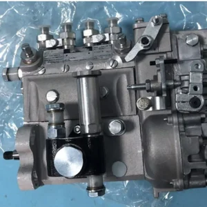
Information injection-pump assembly
BOSCH
9 400 614 528
9400614528
ZEXEL
101495-3332
1014953332
KOMATSU
6204731240
6204731240

Rating:
Compare Prices: .
As an associate, we earn commssions on qualifying purchases through the links below

Fuel Injection Pump 6204-73-1310 6204-73-1240 for Komatsu Engine 4D95L
100% Apollo part number:6204-73-1310 6204-73-1240 || application: for Komatsu Engine 4D95L
100% Apollo part number:6204-73-1310 6204-73-1240 || application: for Komatsu Engine 4D95L

IMIFAFTAbT 6204-73-1240 6204-73-1310 Fuel Injection Pump 6204731240 6204731310 for Komatsu 4D95L 4D95LE Engine
IMIFAFTAbT Part Name:Fuel Injection Pump 6204-73-1240 6204-73-1310 || Part Number:6204-73-1240 6204-73-1310 6204731240 6204731310 || APPlication: Compatible with Komatsu 4D95L 4D95LE Engine || If you are not sure if the product is suitable please leave us a message and send us your original || product picture and part number and we will send the correct part after confirmation
IMIFAFTAbT Part Name:Fuel Injection Pump 6204-73-1240 6204-73-1310 || Part Number:6204-73-1240 6204-73-1310 6204731240 6204731310 || APPlication: Compatible with Komatsu 4D95L 4D95LE Engine || If you are not sure if the product is suitable please leave us a message and send us your original || product picture and part number and we will send the correct part after confirmation

Fuel Injection Pump 6204-73-1240 6204-73-1310 Compatible with Komatsu Engine 4D95L 4D95LE
Starhycfa Product name:Fuel Injection Pump || Part Number:6204-73-1240 6204-73-1310 || APPlication:Compatible with Komatsu Engine 4D95L 4D95LE || 1.Please carefully compare the pictures or OE numbers to match your original parts beCompatible withe purchasing the product. || 2.Please make sure that the model number, part number and photo is the same as yours beCompatible withe order. To Avoid placing wrong orders and wasting your precious time.
Starhycfa Product name:Fuel Injection Pump || Part Number:6204-73-1240 6204-73-1310 || APPlication:Compatible with Komatsu Engine 4D95L 4D95LE || 1.Please carefully compare the pictures or OE numbers to match your original parts beCompatible withe purchasing the product. || 2.Please make sure that the model number, part number and photo is the same as yours beCompatible withe order. To Avoid placing wrong orders and wasting your precious time.
You can express buy:
USD 627.3
14-06-2025
14-06-2025
6204-73-1240 6204-73-1310 Fuel Injection Pump for Komatsu 4D95L 4D95LE Engine
Service parts 101495-3332 INJECTION-PUMP ASSEMBLY:
1.
_

5.
AUTOM. ADVANCE MECHANIS
6.
COUPLING PLATE
7.
COUPLING PLATE
8.
_
9.
_
11.
Nozzle and Holder
6206-11-3100
12.
Open Pre:MPa(Kqf/cm2)
19.6{200}

15.
NOZZLE SET
Cross reference number
BOSCH
9 400 614 528
9400614528
ZEXEL
101495-3332
1014953332
KOMATSU
6204731240
6204731240
Zexel num
Bosch num
Firm num
Name
9 400 614 528
6204731240 KOMATSU
INJECTION-PUMP ASSEMBLY
4D95L * K 14BC INJECTION PUMP ASSY PE4A,5A, PE
4D95L * K 14BC INJECTION PUMP ASSY PE4A,5A, PE
Calibration Data:
Adjustment conditions
Test oil
1404 Test oil ISO4113 or {SAEJ967d}
1404 Test oil ISO4113 or {SAEJ967d}
Test oil temperature
degC
40
40
45
Nozzle and nozzle holder
105780-8140
Bosch type code
EF8511/9A
Nozzle
105780-0000
Bosch type code
DN12SD12T
Nozzle holder
105780-2080
Bosch type code
EF8511/9
Opening pressure
MPa
17.2
Opening pressure
kgf/cm2
175
Injection pipe
Outer diameter - inner diameter - length (mm) mm 6-2-600
Outer diameter - inner diameter - length (mm) mm 6-2-600
Tester oil delivery pressure
kPa
157
157
157
Tester oil delivery pressure
kgf/cm2
1.6
1.6
1.6
Direction of rotation (viewed from drive side)
Right R
Right R
Injection timing adjustment
Direction of rotation (viewed from drive side)
Right R
Right R
Injection order
1-2-4-3
Pre-stroke
mm
3.6
3.55
3.65
Beginning of injection position
Drive side NO.1
Drive side NO.1
Difference between angles 1
Cyl.1-2 deg. 90 89.5 90.5
Cyl.1-2 deg. 90 89.5 90.5
Difference between angles 2
Cal 1-4 deg. 180 179.5 180.5
Cal 1-4 deg. 180 179.5 180.5
Difference between angles 3
Cal 1-3 deg. 270 269.5 270.5
Cal 1-3 deg. 270 269.5 270.5
Injection quantity adjustment
Adjusting point
A
Rack position
11.3
Pump speed
r/min
950
950
950
Average injection quantity
mm3/st.
41
40
42
Max. variation between cylinders
%
0
-2.5
2.5
Basic
*
Fixing the lever
*
Injection quantity adjustment_02
Adjusting point
-
Rack position
9.6+-0.5
Pump speed
r/min
510
510
510
Average injection quantity
mm3/st.
13
12
14
Max. variation between cylinders
%
0
-15
15
Fixing the rack
*
Remarks
Adjust only variation between cylinders; adjust governor according to governor specifications.
Adjust only variation between cylinders; adjust governor according to governor specifications.
Injection quantity adjustment_03
Adjusting point
D
Rack position
15+0.2
Pump speed
r/min
100
100
100
Average injection quantity
mm3/st.
53
43
63
Fixing the lever
*
Rack limit
*
Test data Ex:
Governor adjustment
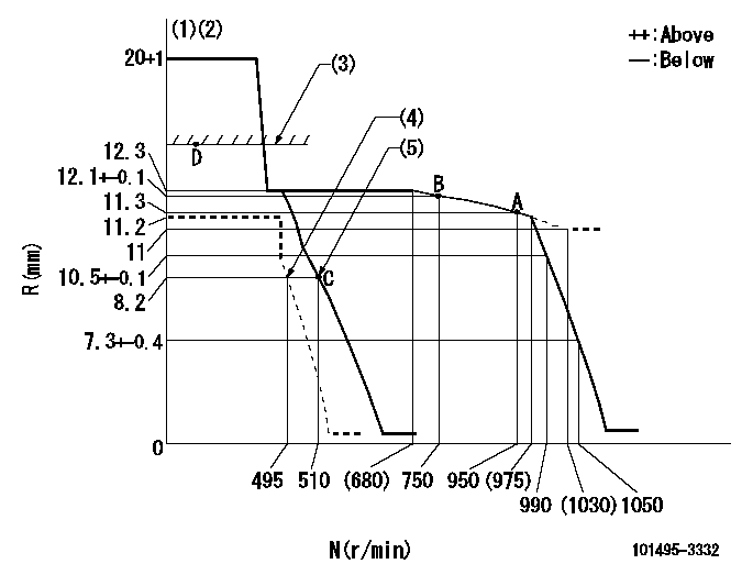
N:Pump speed
R:Rack position (mm)
(1)Target notch: K
(2)Tolerance for racks not indicated: +-0.05mm.
(3)RACK LIMIT: RAL
(4)Set idle sub-spring
(5)Main spring setting
----------
K=10 RAL=15+0.2mm
----------
----------
K=10 RAL=15+0.2mm
----------
Speed control lever angle
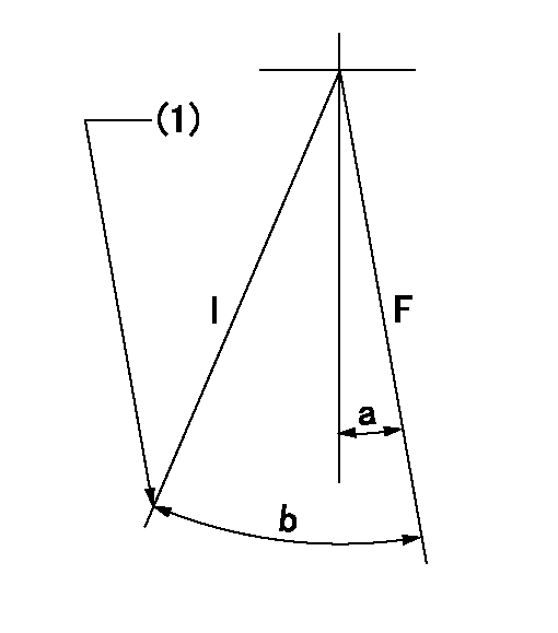
F:Full speed
I:Idle
(1)Stopper bolt setting
----------
----------
a=1deg+-5deg b=20deg+-5deg
----------
----------
a=1deg+-5deg b=20deg+-5deg
Stop lever angle
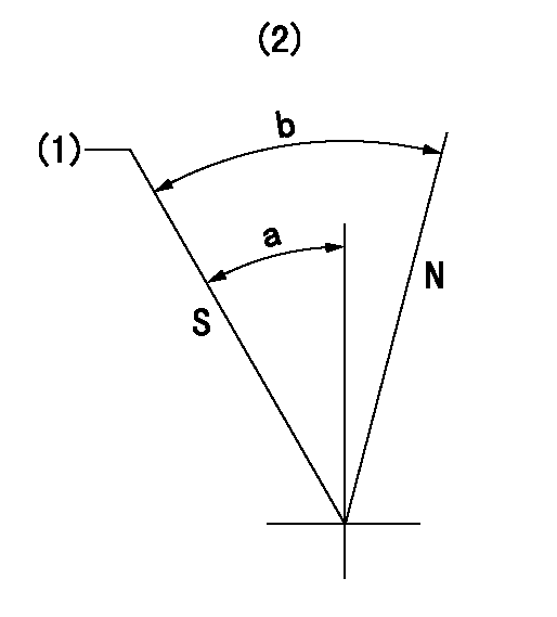
N:Pump normal
S:Stop the pump.
(1)Rack position = aa, speed = bb (stamp at delivery)
(2)No return spring
----------
aa=1-0.2mm bb=0r/min
----------
a=27.5deg+-5deg b=(55deg)
----------
aa=1-0.2mm bb=0r/min
----------
a=27.5deg+-5deg b=(55deg)
Timing setting

(1)Pump vertical direction
(2)Position of key groove at No 1 cylinder's beginning of injection
(3)Stamp aligning marks on the pump housing flange.
(4)-
----------
----------
a=59deg36min+-3deg b=0deg24min+-30min
----------
----------
a=59deg36min+-3deg b=0deg24min+-30min
Information:
Illustration 17 g03389921
Illustration 18 g03389931
Read the warning and select "Accept" to continue.
Illustration 19 g03389947
Once the reset is completed, a log of the reset is captured and visible as a new row of information in the Diesel Oxidation Catalyst Replacement screen. Selective Catalytic Reduction (SCR) Maintenance on Tier 4 Final Products
Note: Refer to Table 5 for the existing SCR catalyst part number being serviced along with the corresponding new service kit, and the clamp part number required for reassembly.
Table 5
SCR Part Number Service Kit Part Number Required Clamp Part Number
447-8145 N/A 346-0335
447-8143 N/A 346-0335
447-8141 N/A 346-0335
447-8149 N/A 346-0335
447-8147 N/A 346-0335
447-8163 N/A 346-0335
447-8151 N/A 346-0335
375-0989 N/A 346-0335
447-8165 N/A 346-0335
447-8153 N/A 346-0335
447-8161 N/A 346-0335
447-8159 N/A 346-0335
447-8157 N/A 346-0335
447-8169 N/A 346-0335
447-8173 N/A 346-0335
447-8171 N/A 346-0335
447-8167 N/A 346-0335
447-8175 N/A 346-0335 The Aftertreatment SCR Catalyst Replacement procedure must be performed when the SCR Catalyst has been replaced. This is necessary to ensure that the engine meets emissions requirements. Follow the procedure below to reset the SCR Catalyst model in the aftertreatment software.
Connect to Cat® ET.
Illustration 20 g03390636
Connect to "Engine #1 Aftertreatment Controller".
Illustration 21 g03740190
Select "Service" from the top menu and select "Service Procedures".
Illustration 22 g03740205
Select "Aftertreatment #1 SCR Catalyst Replacement" and select "Start".
Illustration 23 g03740210
Select "Reset".
Illustration 24 g03740216
You must read the warning and select "Accept" to continue.
Enter the factory passwords to continue.
Illustration 25 g03740230
Once the reset is completed, a log of the reset is captured and visible as a new row of information in the "Aftertreatment #1 SCR Catalyst Replacement" screen.